Well, I wanted to give it a try as my first ads-b antenna and this tiny GP gave me 500Km (i.e. 270nm) of coverage at the first attempt !!
I have to admit that my balcony is at 330m above sea level and I only have the ocean in front of me and this helps a lot
Nevertheless I have no coverage toward the West.
I�m really happy so far but I�m already building a J-pole for more coverage before start feeding FR24 with my brand new Orange Pi PC Plus.
Btw as you can see I kept the cable to the minimum :-)
IMG_20170426_153009.jpg
IMG_20170426_194854.jpg
Thanks abcd567 ;-)
-
Very interesting. Amazing how these small changes in geometry affect performance. Best bet is 45 seems like?
Sent from my Pixel using TapatalkLeave a comment:
-
Please see attached photos. Readings are:Originally posted by joni1101 View Post
(1) Spider with horizontal radials, z=26, swr=1.9
(2) Spider with slanting radials 45 degrees, z=67, swr=1.3
(3) Spider with vertical radials, z=73, swr=2.2
32501334462_b814ba037c_b.jpg . 32654383295_a06f14e4a4_b.jpg . 31811480314_35dc93800a_b.jpgLeave a comment:
-
I did not measure the impedance with radials at different angles, only at 45 degree slanting down.Originally posted by joni1101 View Post
Theoretically horizontal radials have 32 ohms, 45 degree slanting have about 50 ohms and vertical (i.e. a dipole) have 75 ohms.
Practically for ADS-B, I compared message rate for horizontal and 45 degree slanting radials, and noticed only slight increase in adsb message rate with slanting radial. Please see this post:
Why Antennas Have Ground Plane?
Please note that the instrument I have used measures only VSWR/R/X/Reflection S11.
It does NOT measure following important parameters:
1) Antenna Gain
2) Antenna Directivity/Radiation curve
3) Common mode/unbalanced currents in feed coax
The purpose of this instrument is to check:
(1) At what frequency antenna is tuned. The tuned frequency is where the SWR-Frequency curve is at minimum. If it is tuned at lower than design frequency, trim the whip, if tuned at higher frequency, add a piece to whip.
(2) How much is VSWR. If measured VSWR is greater than 1.5, than impedance matching devices should be used. Once the VSWR is below 1.5, its actual value does not matter, then it is the Gain and Directivity which really make difference.Last edited by abcd567; 2017-01-30, 02:07.Leave a comment:
-
Looks like this antenna has very slightly better specs than the Cantenna. Can you affect the impedance by the angle of the spider legs?
Sent from my Pixel using TapatalkLeave a comment:
-
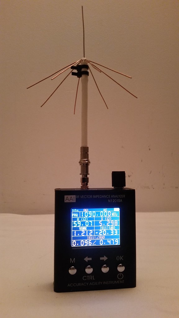
Testing of Quick Spider by Antenna Analyzer
VSWR=1.2, R=59Ω, X=5Ω, and S11=-20 @1090 MHz
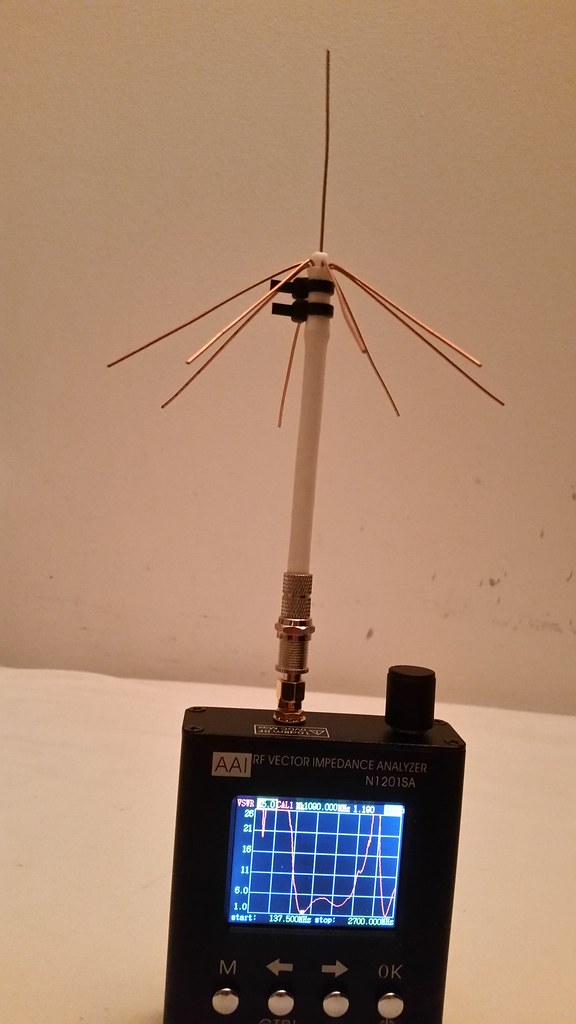
Plot of VSWR vs Frequency 137.5 Mhz ~ 2700 MHz.
Marker at 1090 MHz, minimum SWR at marker
Leave a comment:
-
My Cantenna performs slightly better than Spider, but for some others Spider performs better than Cantenna.Originally posted by joni1101 View Post
Actually it is not the antenna alone. It is (antenna+coax+location) which decides overall performance. Since Cantenna and Spider are very close in performance, any one of the two can perform better than other depending on location & coax length.Leave a comment:
-
Did the quick spider outperform the Cantenna?
Sent from my Pixel using TapatalkLeave a comment:
-
@abcd567:
Yep. My intention is to try that one first as it is extremely easy to build - although your experiences with the Coax Antenna are not too promising [B]as you posted here[/B]. In a second step I'll try your Cantenna (same posting also), which is much more promising as you state there (and also quite easy to set up).
Trials will hopefully start in the next days/weeks, when I find some time. I'll let you know about the results of my attempts.
Greetings from Germany to Canada, and have a nice weekend, -Wolli-Leave a comment:
-
@Wolli
Thank you.
Please post your opinion about the "DVB-T Selbstbau-Antenne" after you make and use it.Leave a comment:
-
@abcd567:
Yes, absolutely correct. To my shame (red ears here) I must admit, that I looked into my Rothammel some months ago and did not find the Coaxial Antenna, although it's clearly listed (and even easily to find!) in this "antenna bible". Well, maybe I was searching for another variant at that time, I don't remember to 100%.
So I think this should work, and I will try out - hopefully within the next few weeks. Possible small mismatches (Rothammel: 60 Ohm cable - my attempt: 75 Ohm cable) won't produce too much loss in signal strength at the receiver's input, as I suppose.
Again many thanks for your feedback - and also a very big THANK YOU for your very impressive postings concerning antennas, e.g. the "Cantenna" and so many more.
Greetings again from Germany, -Wolli-Leave a comment:
-
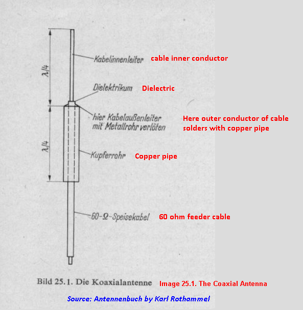
@Wolli
The antenna you want to make is a simplified varient of coaxial antenna ("Die Koaxialantenne"). It is also known as "Sleeved Dipole". Please see the diagram below.
(Translation in english in red and blue colors added by me)
 Last edited by abcd567; 2016-11-23, 02:15.
Leave a comment:
-
@abcd567
Thank you very much for your reply. I agree 100%, it's indeed a very smart antenna solution for the very poor man.
And yes, I of course noticed "no soldering" and "no connector" (the "poor man's" used by myself needs soldering and connector) - a very charming solution.
As being a friend of "simple antennas", I consider to make an attempt in the near future with plain 75Ohm SAT cable, like introduced here (sorry, in German language, but the pictures on this site themselves should however show, what I'm planning to do). The centre core around 65mm long, and the shield (with length also around 65mm) "rolled back" over the plastic jacket.
This should - hopefully - produce an antenna impedance of @75 Ohms (very roughly, of course), corresponding to the SAT cable's impedance.
I'm interested in your thoughts about this (possible) solution. Please feel free to comment, if you like.
This solution is - of course - not very suitable for DXing, but for omnidirectional reception in the "near field" (radius let's say up to @100 NM) it seems very promising to me.
Greetings from Germany to Canada, -Wolli-Leave a comment:
-
@ Wolli
(1) The main difference between "poor man's ground plane antenna" and "Quick Spider" is that "poor man's" antenna requires a SO239 or N connector, whereas "Quick Spider" does not require any connector, and therefore can be called "very poor man's ground plane antenna"
(2) The "poor man's ground plane antenna" is itself a variant of "ground plane antenna" which existed since the time radio communications were started at beginning of 20th century, but it used a heavier mechanical construction to support radials, instead of a VHF/UHF connector used by K2RIC in 1957.
By the way, the very first antenna of the world was invented by German scientist Heinrich Hertz in 1886, and it was a 1/2 wave dipole (CLICK HERE).Leave a comment:
-
I like the "simple" antennas, like this one. Thank you very much indeed for your posting.
It's a variation of the "poor man's ground plane antenna", described by K2RIC in 1957 in "CQ (USA)".
I use another variation - with just 4 radials - here on my side. Cable however is just 50 Ohms (RG 58), but working quite well with my FR24-feeder.
Here a website (in German language) showing how to build a comparable "poor man's gp" (although not for 1090 MHz, but the idea of manufacturing is the same, just other dimensions):
-> http://www.qsl.net/dl2lux/sat/gpa.html
He used an N connector for build (pictures 2A and 2B in the linked webpage) - I used a BNC connector. Very cheap - for the "poor man". And doing the job quite well.
Last edited by Wolli; 2016-11-15, 21:52.
And doing the job quite well.
Last edited by Wolli; 2016-11-15, 21:52.Leave a comment:
Leave a comment: