Announcement

Collapse
No announcement yet.

best antenna

Collapse
X
 
  • Filter
  • Time
  • Show
Clear All
new posts

  • Whip2.JPG

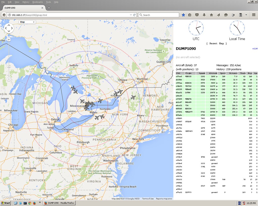
    I have been using this whip antenna for a while, it is a 3 element wire collinier, when covered with heatshrink it was detuned and needed 60mm trimmed from the top. Now it works perfectly. I also made a 9 element in the same way but the detuning from heatshrink was more severe, and there is not enough top element to trim down. I have been using this whip without any insulation material so it is affected by rain which detunes it .

    Whip.jpg

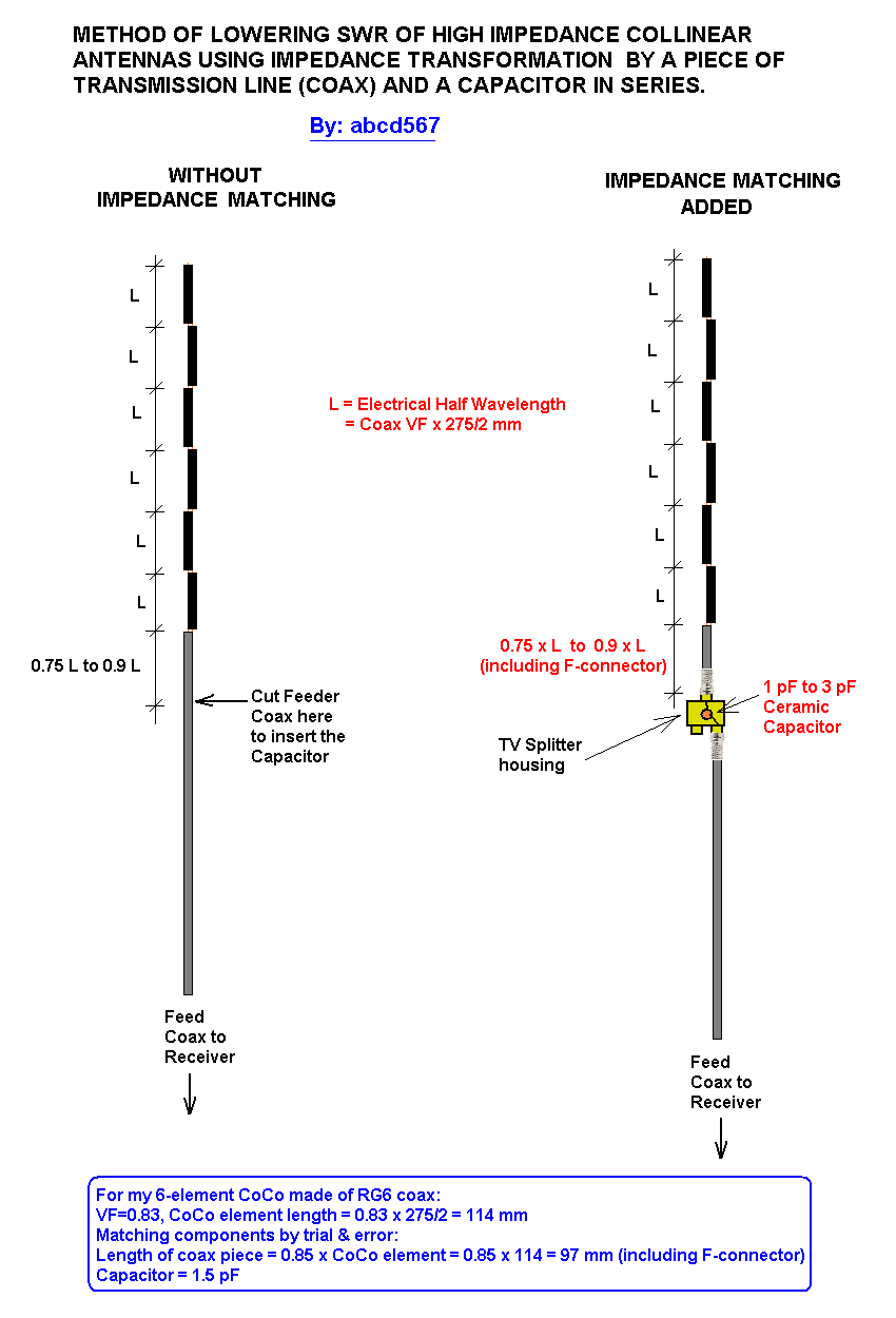
    I have been working on the de-tuning effect and the velocity factor of heatshrink , and have made another antenna, this time I have used a velocity factor of .94
    I re-calculated all the formulas for the elements and the coils at .94 percent and covered it with heatshrink. Testing today and its working good, but I will need to do some trimming to get it A1 . Will report findings
    Mike
    Burnie, Tasmania

    Comment


    • IMPROVING PERFORMANCE OF A COCO BY LOWERING IT's SWR/IMPEDANCE
      It is well known that a large number of DIY CoCo makers get frustrating results, and only a relatively small number get satisfactory or good results. Main reason is high impedance & resulting high SWR which causes the antenna to perform poorly even if it has a high Gain.

      I have tried to find a method to ease out the SWR without using test instruments. I tested it and it gave me an improvement of about 25 to 35%., not optimal, but better than nothing.

      Please see sketches below showing an example of impedance matching using this method. It results in using a piece of coax between 0.75 to 0.9 of the length of halfwave elements of CoCo, and a 2.5 pF Capacitor in series. It is applicable to most CoCos without using test equipments. It requires trying four pieces of coax of lengths (0.75 x VF x 138 mm), (0.8 x VF x 138 mm), (0.85 x VF x 138 mm) and (0.9 x VF x 138 mm), and keep the one which give better results than others. The length of coax piece includes length of F-connector also.

      SKETCH 1 of 2 : IMPEDANCE TRANSFORMATION BY A PIECE OF COAX 0 to 1/2 WAVELENGTH LENGTH


      SHETCH 2 of 2: IMPEDANCE MATCHING / SWR IMPROVEMENT METHOD


      This method uses the fact that a piece of transmission line (Coax) transforms the impedance of antenna connected to it. The value of impedance seen at other end of coax depends on length of piece of coax. The impedance transforms in a cyclic manner, returnig back equal to antenna impedance every 1/2 wavelength. At a particular length in between 0 and 1/2 wavelength, the Resistance transforms to exactly the impedance of coax/receiver, and reactive component transforms from capacitive to inductive. At this point if a capacitor of appropriate value is inserted to cancel the inductive component to zero, only resistive component remains which is equal to system impedance, and stays same along remaining entire length of feed coax.

      .
      Last edited by abcd567; 2015-08-10, 09:33.

      Comment


      • .
        GRAPHICAL REPRESENTATION - IMPEDANCE TRANSFORMATION ALONG LENGTH OF COAX

        Comment


        • Today I made a new 6-element CoCo. I put it to test WITHOUT amplifier and 12ft/ 4m piece of RG6 coax between CoCo and DVB-T USB Dongle + RPi combo. As usual results were poor (see Image 1 of 3).

          I then inserted a capacitor (1.5 pF ) and a piece of coax (length = 0.85 x 1/2 wavelength) between feed cable & CoCo, bringing it's Impedance down, and thereby improving its SWR. The performace increased considerably (see Image 2 of 3).

          I found the length of coax piece & value of capacitor by trial & error, and a few trials only. If I would have tried more lengths & capacitors, I might have got even better results. The rule of thumb I use is that coax piece's optimum length is somewhere between 0.75 to 0.9 of 1/2 wavelength element of CoCo, & the capacitor 's optimum value lies somewhere between 1 pF and 3 pF.

          Please see Image 3 of 3 showing the impedance matching arrangement.

          The two screenshots of dump1090's gmap were taken with a difference of 2 minutes only, the time taken to insert/remove the capacitor.

          IMAGE 1 of 3- dump1090 gmap, NO Impedance Matching, NO Amplifier


          IMAGE 2 of 3 - dump1090 gmap, WITH Impedance Matching, NO Amplifier


          IMAGE 3 of 3 - Impedance Matching Arrangement

          Comment


          • Any photo showing the connection for the ceramic capacitor?

            Comment


            • u must have a lot of antennas.....a lot.....got enough spare time to do all tests...dok gitu....

              Comment


              • Originally posted by kucengemok View Post
                Any photo showing the connection for the ceramic capacitor?
                Here is the photo:
                Ceramic Capacitor in TV Splitter Housing.PNG

                Comment


                • May give that a go! Should be a few dollars for the ceramic capacitor (may have one in some old equipment somewhere) and the two way splitter shouldn't be any more than AU$10. If I can get a 5% improvement, I'd be happy and any more is a bonus.
                  F-YSWG1 and T-YSWG2

                  Comment


                  • @YSWG: For your information.

                    2-WAY CABLE TV SPLITTER 5-900MH Digital Analogue Satellite Coaxial Out Connector

                    AU $1.49
                    Free postage
                    From Hong Kong


                    150 Pieces 50V 1PF Ceramic Disc Capacitors Replacement Brown

                    AU $4.23
                    Free postage
                    From Hong Kong


                    1000pcs 50 Values 50V Ceramic Capacitor Assorted kit Assortment Set 1pf-100nf

                    AU $6.41
                    Free postage
                    From Hong Kong

                    Comment


                    • Originally posted by YSWG View Post
                      May give that a go! Should be a few dollars for the ceramic capacitor (may have one in some old equipment somewhere) and the two way splitter shouldn't be any more than AU$10. If I can get a 5% improvement, I'd be happy and any more is a bonus.
                      You will need to prepare several pieces of coax 0.75, 0.8, 0.85, & 0.9 times half wavelength (half wavelength = VF of coax X 138 mm).
                      Start trial by mid range values i.e. Coax piece 0.85 x 1/2 wavelength, and capacitor 2 pF. Then try different pieces. Once you find the piece which gives best performance, start trying different values of capacitor like 1 pF, 1.5 pF, 2pF, 2.5pF.

                      Note: Length of coax piece includes length of F-connector.
                      Last edited by abcd567; 2015-08-25, 19:29.

                      Comment


                      • Picked up [locally] the two way spitter for AU$13 and the ceramic capacitors in a pack of two for 38 cents. Will need to rebuilt an antenna and fix the cable between the dongle ant antenna.
                        F-YSWG1 and T-YSWG2

                        Comment


                        • Originally posted by YSWG View Post
                          Picked up [locally] the two way spitter for AU$13 and the ceramic capacitors in a pack of two for 38 cents. Will need to rebuilt an antenna and fix the cable between the dongle ant antenna.
                          It seems you purchased a very good quality splitter, that is why you paid almost 9 times the price of a cheap quality one.

                          Since only the housing of splitter will be used, and the internal electronics will be removed and thrown in garbage, there is no use purchasing a very good quality splitter at 9 times the cost of a cheap one.


                          Is this you YSWG?

                          Comment


                          • Hi all,

                            Can you tell me the parts list said in this project? Or any link to describe this more detailed.
                            Frontend Filter and LNA Design for the reception of Aircraft ADS-B signals. CC-BY-SA - Reid-n0rc/ADS-B_LNA_Project

                            IMG_20150729_081738584.jpg

                            Thanks in advance,
                            Zahidul Hasan.

                            Comment


                            • Been unable to make the antenna but used the current six element CoCo with 1m of coax before the 2.7pF ceramic capacitor. Noticed an increase in messages by 5-7% but decreased by 40% thanks to rainwater getting into the two-way splitter.

                              dump1090-rpi-rate-6h.png
                              The sharp rise at about 16:30 on the 31st was when I added it
                              dump1090-rpi-rate-24h.pngdump1090-rpi-rate-1h.png
                              Today's decrease is noticeable
                              Last edited by YSWG; 2015-09-03, 09:43.
                              F-YSWG1 and T-YSWG2

                              Comment


                              • Originally posted by zahidulhasan View Post
                                Hi all,

                                Can you tell me the parts list said in this project? Or any link to describe this more detailed.
                                Frontend Filter and LNA Design for the reception of Aircraft ADS-B signals. CC-BY-SA - Reid-n0rc/ADS-B_LNA_Project

                                [ATTACH=CONFIG]6383[/ATTACH]

                                Thanks in advance,
                                Zahidul Hasan.
                                on the link you posted the are four links the bottom one is csv file of all the parts.

                                two 100pf caps
                                one 22k resistor
                                one 604 ohm resistor
                                one Bipolar - RF Transistor

                                the pdf files are what you need to make your own PCB.
                                T-EGLF8

                                Comment

                                Working...
                                X