Originally posted by K5TED
View Post
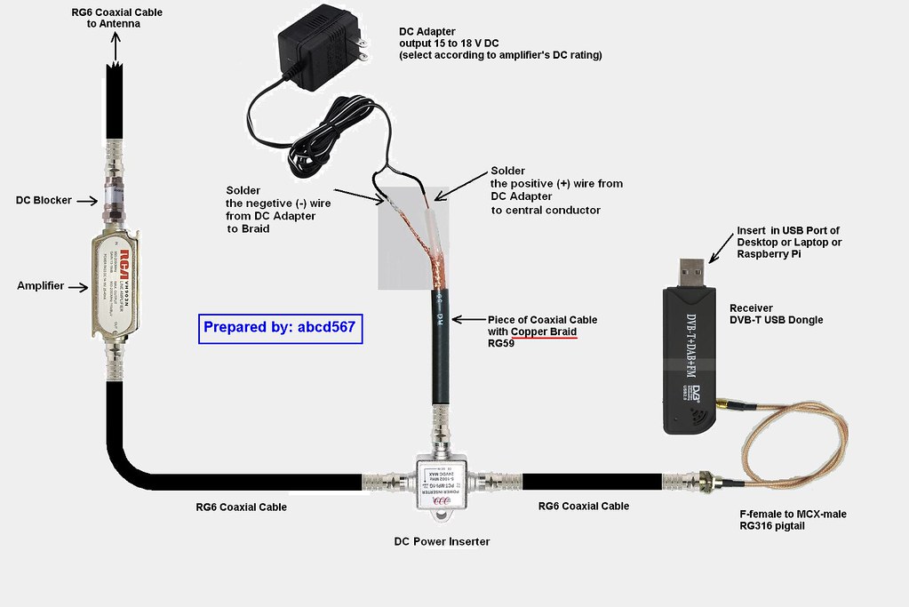
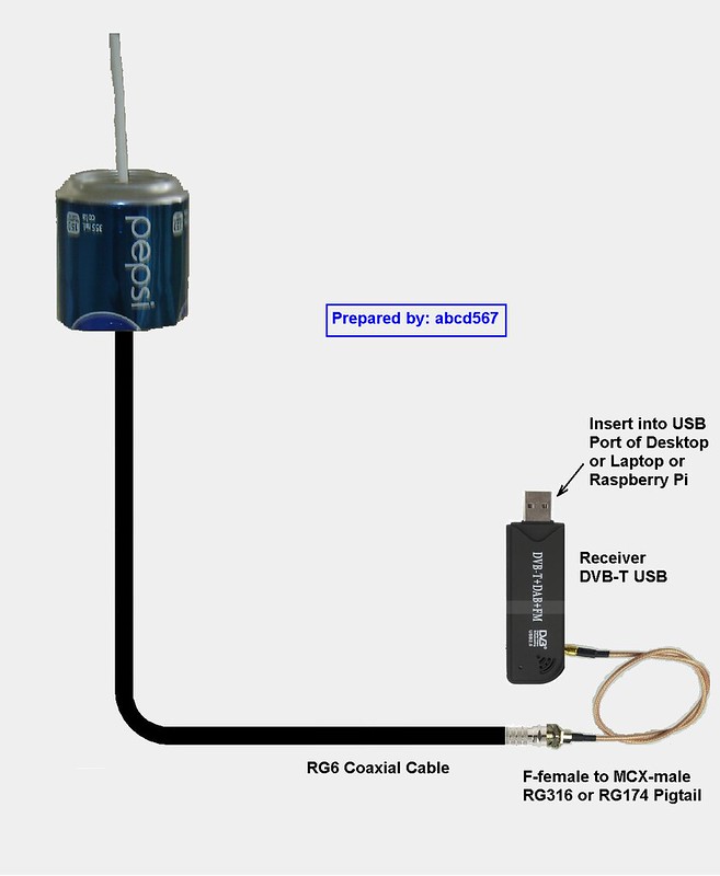
Lots of great antenna ideas here. The wonderful thing about 1090MHz is the antennas are very small. This allows lots of experimenting with little actual materials needed, unlike HF or even VHF antennas. At 1090, the cables and connectors are more elaborate and costly than the actual antenna materials.
With experimention in mind, here's an antenna design that outperforms the supplied whip, and requires no more than a BNC barrel connector and a few cm of 24g solid copper wire, in this case, a strand from a piece of CAT5...
The Delta Loop. This can be positioned and fed in many different configurations with varying pattern results:
[ATTACH=CONFIG]6789[/ATTACH]
The orientation and feed methods:
[ATTACH=CONFIG]6790[/ATTACH]
Basic design is using 10cm per side at this frequency. Check for "delta loop calculator" on the web for reference. There are many wire antenna possibilities that can be pressed into testing for 1090, including quads, loops, moxons, etc. .
I found this commercial MaxRad RDS antenna on ebay for the princely sum of $8 USD. It is originally designed for 800MHz, but it was a simple matter to trim the radiator and radials down to 1090 :
[ATTACH=CONFIG]6791[/ATTACH]
These were still available as of today, so if you decide to try this antenna and want to trim it down, I took one completely apart and got the dimensions so you don't have to:
1. Radiator is pressed in to the hardline center. DO NOT ATTEMPT TO TWIST AND REMOVE IT. Trim it in place. It protrudes 81mm from the center conductor (measured with cover off) Remove the black plastic bootie and trim accordingly from the tip. (13mm for a 68mm adjusted length)
2. Ground Radials are 84mm long and threaded into the aluminum base ring, measured observing the three to 4 threads left exposed. Remove the black plastic bootie and trim accordingly from the tip. (16mm for a 68mm adjusted length)
If you insist on taking it apart to see the guts, after the three radials are unscrewed and removed, the assembly slides out of the cover. It is a bit fiddly to get the threads all lined up when putting it back together. Remember this is aluminum, so be gentle.
The antenna works well, in my estimation, set at about 25' in a window for now, can get up to 178 miles South and about 150 North. It'll be interesting to see how it does mounted in an enclosure outside with a clearer view to the East and West.
I'm a newbie to ADS-B, but a longtime amateur radio hobbyist, so this is a refreshing new facet. Currently using a Noelec 820T2 RTL with an Intel Compute Stick, running Win 10Pro, Dump1090, Virtual Radar Server and feeding FR24. site is T-KSAT6


Leave a comment: