it is possible to get clear acrylic tube in various diameters maybe something could be constricted to fit over the frankin by slitting such a tube to slip over and using mitre joints etc. use polystyren packing beans as spacers every so often. coke bottle tops (glued on) at the open ends. glue to weld the joins.
Announcement
Collapse
No announcement yet.
best antenna
Collapse
X
-
2L pop bottle is about 4 inch wide... how about slicing the top and bottom off, leaving a cylinder - then gluing (or even taping with duct tape on the inside) several together ? to make a LONG pop bottle !
Another radome Ive used in the past are fishing rod tubes... about 3in diameter and 2 meters long ! Here in the UK these can be had for about £3.
Comment
-
(1) Fishing Rod Tube (3 inch dia) is a good idea, not very costly, and easier than assembling the pop bottles.Originally posted by Rooster View Post2L pop bottle is about 4 inch wide... how about slicing the top and bottom off, leaving a cylinder - then gluing (or even taping with duct tape on the inside) several together ? to make a LONG pop bottle !
Another radome Ive used in the past are fishing rod tubes... about 3in diameter and 2 meters long ! Here in the UK these can be had for about £3.
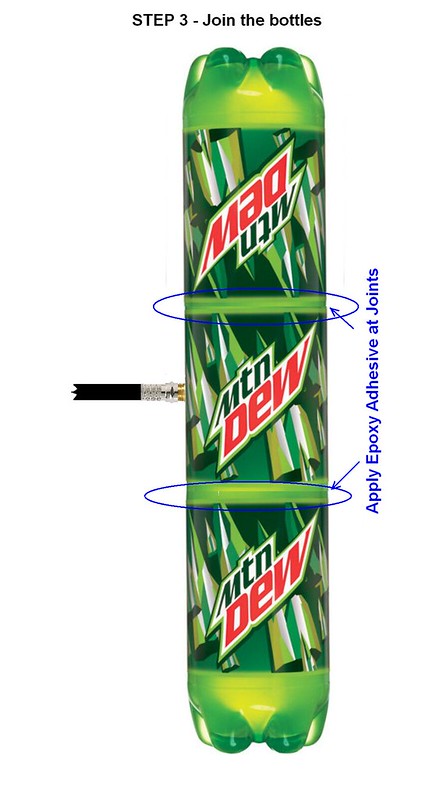
(2) The 2 Liter Lemonade Bottle concept translated to picture.
NOT an actual assembly. Done in Photoshop
here 3 bottles are shown. If longer length required, more middle section can be added.


 Last edited by abcd567; 2014-10-09, 18:22.
Comment
-
Hi ab cd, is it imperative that the phasing and the matching stubs are separated by air? When it rains, small bits of water collect in the stubs and drastically reduce the plane count. Once the stubs dry out again things return to normal. I have some beeswax and was wondering if filling the gaps with this would destroy the gain?
The beeswax idea didn't work for 2 reasons:
1) the max distance dropped from 150nm to 50 nm
2) the local bees turned up to reclaim their wax. Within 24 hours the stubs were clean
Looks like a drink bottle radome is the answer.T-EGUB1
Comment
-
I personally prefer fishing rod holder tube 3" dia suggested by Rooster, as it does not require any gluing of bottle parts, and hence is easier and durable.Originally posted by trigger View PostHi ab cd, is it imperative that the phasing and the matching stubs are separated by air? When it rains, small bits of water collect in the stubs and drastically reduce the plane count. Once the stubs dry out again things return to normal. I have some beeswax and was wondering if filling the gaps with this would destroy the gain?
The beeswax idea didn't work for 2 reasons:
1) the max distance dropped from 150nm to 50 nm
2) the local bees turned up to reclaim their wax. Within 24 hours the stubs were clean
Looks like a drink bottle radome is the answer.
However if you want to use pop bottle, make sure to use good adhesive or tape to hold the parts together against rain, sun & wind.
Of all the glues/adhesives I have used, I have found slow-setting, two-part Epoxy Resin adhesive (long ago known as "Araldite" by CIBA-GEIGY, and was supplied in two tubes, "resin" & "hardener", which were mixed thoroughly and then applied within 15 minutes after mixing). The Fast-setting or 5-minutes/10 minutes Epoxy do not give the strength as the slow-setting one, which takes 12 to 24 hrs to set, depending on room temprature, higher tempratures reduce setting time.
Slow-setting Epoxy Resin is a bit messy, and due to slow-setting, tends to flow out and drip from the joint before it become hard enough to prevent flow.
Comment
-
Back to School.........oops... back to CoCo
After more than half a dozen failed CoCos built by me, I got frustrated and quit the CoCo, concentrating on other designs.
I could not quit the big "Why", and it kept on pinching me. So I decided to postmortem the issue again, this time not by making it, but analyzing by theory & simulation.
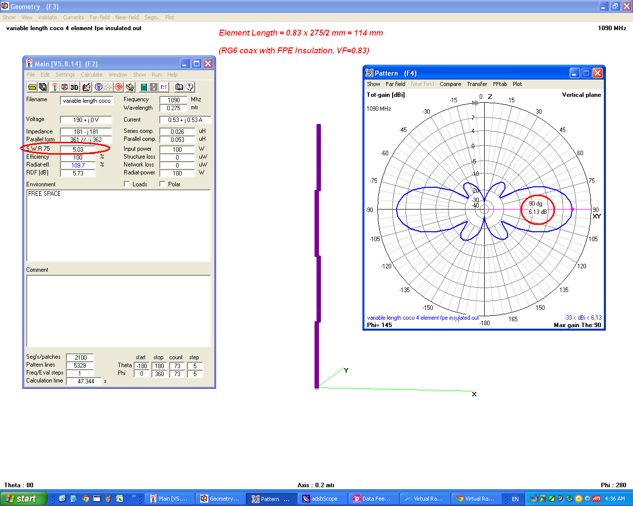
Previously I have done simulation of CoCos made of "Air Insulated" coaxial elements to avoid affect of VF assumption. Since this is not a practical situation, as most of us use normal Coaxial cable with insulation, I decided to model a 4-element CoCo with RG6 cable, FPE Insulation, 0.83 V.F.
I also made it possible to vary the length of elements, to see the effect of changing the length to determine what is the effect of length error on gain & swr.
The simulations showed two things:
(1) The Gain & SWR do not change appreciably with few mm error in length.
(2) CoCo being composed of an array of half-wave elements, its impedance is high.
At this stage, my conclusion is that failure of DIY CoCo is NOT due to errors in VF assumption, or length errors. It is mainly due to high impedance, resulting in impedance mismatch & high SWR.
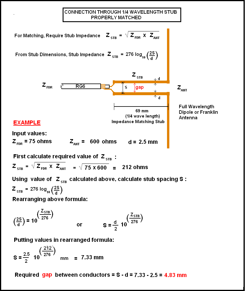
The DIY hobbyists normally do not have instruments to measure the impedance/swr of their finished antenna, nor are aware of techniques to bring down the impedance (installing antenna tuner/Coil/Variable Capacitor/Stubs etc at feed point). The DIY hobbyist's antenna therefore gives poor results.
I am now trying to find an easy to make DIY impedance matching method for hobbyists. As first step, I plan to run the simulation after adding a 1/4 wave element at top to act as matching stub and see it's effects.
I also plan to see the effect of increasing the gap between elements where they join. In my simulations I have kept this gap 0.5mm, enough to insert a piece of PVC Tape or paper between the pieces to prevent short.
Need some free time to do this, maybe this weekend, or next.
Gain, SWR, Pattern at element length of 114 mm (by standard formula Length =VF x 1/2 wavelength, where VF=0.83 for RG6 Cable with FPE Insulation).

EDITED on October 13, 2014:
Simulation revised, as by mistake in previous simulation the value of VF was entered instead of value of Dielectric ConstantLast edited by abcd567; 2014-10-13, 14:09.
Comment
-
What is it with Aircraft and beekeeping? I also keep bees and know 2 glider pilots who are beekeepers!Originally posted by trigger View PostI don't need any honey as I'm a beekeeper. This year the bees have produced about 150lbs honey and loads of beeswax
Ben.
Nb not as good a year for me, about 100lbs from one hive and only 50lbs or so from the other,FR24 F-EGLF1, Blitzortung station 878, OGN Aldersht2, PilotAware PWAldersht, PlanePlotter M7.
Comment
-
Flying things? We do have an ex BA pilot in our association.Originally posted by F-EGLF1 View PostWhat is it with Aircraft and beekeeping? I also keep bees and know 2 glider pilots who are beekeepers!
Ben.
Nb not as good a year for me, about 100lbs from one hive and only 50lbs or so from the other,T-EGUB1
Comment
-
Hi ab cd,Originally posted by abcd567 View PostBack to School.........oops... back to CoCo
I think it is awesome that you are back to coco modelling, I myself am not working an adsb (1090MHz) antenna, but have read through this thread with interest to be able to better understand OGN antennas (868.3MHz).
After seeing your "new" formula i immediately understood why and tried to model it in 4nec2. however i could not find out how you modeled the coax (any tips on that, or some work i can use as a basis would be appreciated.)
So instead i took the Franklin collinear example and changed it so i can vary the vf, have the phasing stubs the correct calculated size (1/2Lambda) and the straight pieces shorter (1/2Lambda*vf).
i found that the shape and gain vary significantly with change in vf. is it possible for you to do a sweep in vf on your coco model?
I myself have made 3 868.3MHz Coco's using .66 VF cable, 2 of them have given me pretty good results, and one of them is hardly usable. All of them where connected with only minimal length of cabling (20cm or so).
I have a small feeling that a short at the top with a 1/4Lambda piece sticking out of it has brought the best result however there might be other factors contributing. This might be worth a simulation also.
I hope that we will be able to master the dark art of cocos.
Benjamin
Comment
-
[QUOTE=abcd567;57100]@ gregy:
Franklin 4-element antenna.
wire dia = 2.5mm, gap between conductors of phasing & impedance matching stubs = 5 mm.
Gain = 5.8 dBi, SWR (50 ohms) = 2.37.
Hi ABCD567
finished the franklin (brass rod 2.5mm) - couldnt make from single peice rod - too difficult to get all dimensions accurate.
made from 3 peices and silver soldered them together (assuming that this doesnt change the characteristics - provided engths correct) - easiest to bend the stubs first & then adjust the rest - hence the two "welds".
I attached coax at indicated location - and also tried moving it back and forth, but as predicted this was about best
VSWR (using VNA swept 1050-1130) was around 2.0 ... i was able to adjust this (a little) by adjusting the stub match gap ...
i checked all dimensions and discovered its simply impossible to get a reliable 5mm gap between stub wires (smaller bend radius snaps brass, eventual gap between rods was closer to 5.8mm)
... anyway
put it up and tested ...it worked ... buy very inferior range to my coax coco (1/2" heliax, 4.5 elements - 1/4 + 1/4 on top )
range was at best about half that with coco.
Conclusions - brass becomes brittle when bent into tight radius, even if antenna had worked well, I doubt it would have longevity.
AFter very careful measuring and adjusting to get length of stubs and radiator sections very accurate, ... the stub gaps and radius are
clearly very important to phasing ... and require quite a bit of trial error to achieve bending accuracy.
Im going to have another crack at a second coco ... another 4.5 elements ... to see check reproducibility and performance vs first....
and then may combine them appropriately into an 8.5 to compare ...
Comment
-
[QUOTE=gregy;57712](1) Your results are as I expected with 2.5mm brass rod due to its inability to be bent in sharp radius required for proper impedance matching. The impedance matching is critically dependent on the gap between stub conductors.Originally posted by abcd567 View Post@ gregy:
Franklin 4-element antenna.
wire dia = 2.5mm, gap between conductors of phasing & impedance matching stubs = 5 mm.
Gain = 5.8 dBi, SWR (50 ohms) = 2.37.
Hi ABCD567
finished the franklin (brass rod 2.5mm) - couldnt make from single peice rod - too difficult to get all dimensions accurate.
made from 3 peices and silver soldered them together (assuming that this doesnt change the characteristics - provided engths correct) - easiest to bend the stubs first & then adjust the rest - hence the two "welds".
I attached coax at indicated location - and also tried moving it back and forth, but as predicted this was about best
VSWR (using VNA swept 1050-1130) was around 2.0 ... i was able to adjust this (a little) by adjusting the stub match gap ...
i checked all dimensions and discovered its simply impossible to get a reliable 5mm gap between stub wires (smaller bend radius snaps brass, eventual gap between rods was closer to 5.8mm)
... anyway
put it up and tested ...it worked ... buy very inferior range to my coax coco (1/2" heliax, 4.5 elements - 1/4 + 1/4 on top )
range was at best about half that with coco.
Conclusions - brass becomes brittle when bent into tight radius, even if antenna had worked well, I doubt it would have longevity.
AFter very careful measuring and adjusting to get length of stubs and radiator sections very accurate, ... the stub gaps and radius are
clearly very important to phasing ... and require quite a bit of trial error to achieve bending accuracy.
Im going to have another crack at a second coco ... another 4.5 elements ... to see check reproducibility and performance vs first....
and then may combine them appropriately into an 8.5 to compare ...
(2) CoCo made of Heliax should be better than one made by RG6. The corrugated sheath of Heliax effectively increases the length of radiator (shield).
In CoCos, the element's PHYSICAL length is V.F times 1/2 wavelength. This makes the core's ELECTRICAL length = 1/2 wavelength, but the shield's ELECTRICAL Length becomes less than 1/2 wavelength as shield has VF=1 (shield is surrounded by air in which the arriving RF waves are contained). The CoCo still works, but with reduced gain.
The corrugations in Heliax's shield increase the length of shield, and to great extent compensate the reduction of shield's length. The CoCo made of Heliax therefore gives better results than one made of RG6 or RG58 or any other smooth shield coax.
Waiting for results of crack on your second coco......Last edited by abcd567; 2014-10-11, 20:51.
Comment


Comment