Announcement

Collapse
No announcement yet.

best antenna

Collapse
X
 
  • Filter
  • Time
  • Show
Clear All
new posts

  • hi abcd567

    pls dont take my response as criticism - it was not intended, and yes agree that you have managed the situation
    within the chosen parameters.
    my comment was refering only to the aspect of trying to compensate for the signal loss thru walls, glas etc. using
    amp gain.

    in respect to the SDR reciever - you are correct in that it has poorer reciever characteristics as c/w with
    the others you mention - i never claimed otherwise, however pls understand there is a differnece between gain (to which
    i reffered) and the other parameters you mention. it is however a fact that the dongles have high gain ... and usually the gain needs to be below the max for optimum results. (eg in RTL1090 overide auto and set the gain to max ... and watch the range reduce)
    and i have to respectfully disagree with your statement about noise .... noise comes from many "local" sources in and
    around your home, in addition to "thermal noise" and noise internally generated within dongle. this can easily be seen by using dongle with
    a sdr program as a reciever ... observe the noise floor - with NO antenna connected... and observe how the noise floor rises
    as you increase the dongle gain.
    im sure you or a neighboor has a microwave oven, CFL lights, fluorescent lights, low voltage lights, wall wart power supplies (switchmode) for mobile phones , PC, notebook, .. and so on. .. including dongle power supply noise, which can be partic bad when
    powering dongle from PC USB source
    all of these are "local " sources of noise... (wideband noise)
    yes you are correct - cell phone towers and the like add noise also . (i am on the boresite of a local tower less than 70m away!)

    the performance of the reciever is a function of many factors inc those you mention, and yes for an extremely modest
    Rx cost, the dongles provide great value (and thats what im using), they have a high gain preamp etc but poorer specs
    (compared with purpose built rx) in other areas.
    Comment


    • Originally posted by gregy View Post
      hi abcd567

      pls dont take my response as criticism - it was not intended, and yes agree that you have managed the situation within the chosen parameters................
      Thank you for your detailed reply. I never took your comments as criticism (though I am open to criticism also). I just wanted to make it clear to all forum members that my line of action was based on my circumstances and should not be followed blindly in every situation.
      Last edited by abcd567; 2014-10-01, 04:32.

      Comment


      • @Stephen P:
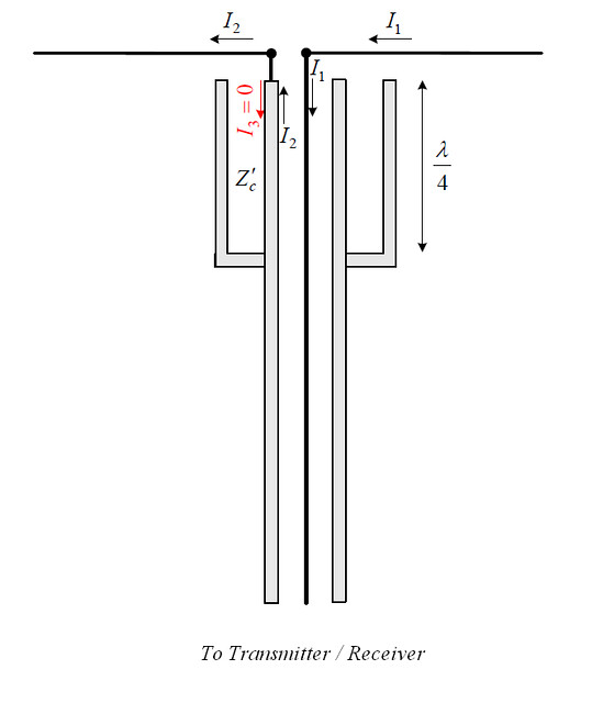
        Another Balun to suppress common mode currents.
        Here it is shown installed at feed point of a Dipole.
        It is also commonly installed at the bottom (feed point) of CoCos.

        Sleeve (bazooka) balun 1:1
        The sleeve and the outer conductor of the coaxial feed form another coaxial line, which has a characteristic impedance of Z′c. This line is shorted quarter-wavelength away from the antenna input terminals. Thus, its input impedance is very large and results in: (i) suppression of the currents on the outer shield (I3), and (ii) no interference with the antenna input impedance, which is in parallel with respect to the coaxial feed. This is a narrowband balun, which does not transform the impedance (1:1 balun).

        Last edited by abcd567; 2014-10-01, 18:31.

        Comment


        • An interesting & informative discussion about CoCo ....
          You can get good information if you read the full page.

          A few questions about collinear coaxial antennas

          https://groups.google.com/forum/#!to...na/DREJnRznluQ

          Comment


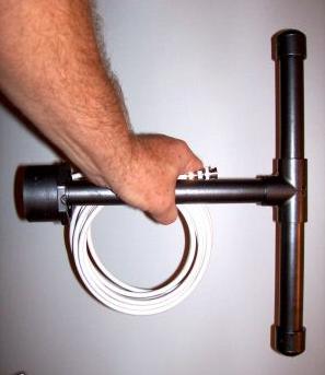
          • Example of a Dipole (halfwave, fullwave, coil loaded etc) inside a PVC pipe Radom

            Comment


            • Originally posted by abcd567 View Post
              An interesting & informative discussion about CoCo ....
              You can get good information if you read the full page.

              A few questions about collinear coaxial antennas

              https://groups.google.com/forum/#!to...na/DREJnRznluQ
              Fascinating discussion. I understood perhaps 1 word in 50
              T-EGUB1

              Comment


              • Originally posted by abcd567 View Post
                Example of a Dipole (halfwave, fullwave, coil loaded etc) inside a PVC pipe Radom

                Classic way of how NOT to do it....
                Black pipe is white pipe loaded with carbon - reactive to RF ! MASSIVE attenuation at best, interaction with the antenna is guaranteed.

                Comment


                • Originally posted by Rooster View Post
                  Classic way of how NOT to do it....
                  Black pipe is white pipe loaded with carbon - reactive to RF ! MASSIVE attenuation at best, interaction with the antenna is guaranteed.
                  looks nice though

                  Comment


                  • Originally posted by Rooster View Post
                    Classic way of how NOT to do it....
                    Black pipe is white pipe loaded with carbon - reactive to RF ! MASSIVE attenuation at best, interaction with the antenna is guaranteed.
                    Found it here: http://www.machine--tools.com/By-Man...dio-shack.ASPX

                    Originally posted by peterhr View Post
                    looks nice though
                    Yes, looks nice. That's what attracted me to post it.. and further, I have never seen before a pipe radome for a center-fed antenna.
                    I don't know what technique the maker used to assemble three parts inside the pipe's Tee (i.e. the upper limb + lower limb + coax connection)

                    Comment


                    • Originally posted by trigger View Post
                      Fascinating discussion. I understood perhaps 1 word in 50
                      Yes, this discussion is quiet techy and requires some background in RF (Radio Frequency) theory.

                      The discussion also refers to use of RF Network Analyzer, which is generally not available to most hobbyist (Cost of RF Network analyzer $4000++). Both Thomas & Jerry of the referred discussion seem to have used it at their workplaces.

                      Download document "Network Analyzer Basics": http://cp.literature.agilent.com/lit...5965-7917E.pdf

                      Comment


                      • In my earlier post #1278, I have mentioned that by using V.F. of insulation in CoCo, we make element interior (core) 1/2 wavelength. This shortening of element also makes shield less than 1/2 wavelength (as shield is outside the core insulation and its VF is 1). For proper phasing, both shield & core should be half wavelength.

                        Now I found this post in eham forums, who has same opinion as mine:

                        http://www.eham.net/ehamforum/smf/in...0104#msg250104
                        Last edited by abcd567; 2014-10-05, 02:13.

                        Comment


                        • People's opinion about CoCo:

                          "End fed colinear antennas are convenient but far from ideal. They're also deceptively simple where the problems only show up after the antenna is built."

                          "i did start making one of these coax antennas but got tired with messing with bits of coax and as it was simply only to make for the sake of it and not to be used gave up.. "

                          "Most of the designs for coaxial collinear antennas are very poor designs. They are very poor copies of Phelps Dodge's Station Master series. I've built several from Ham articles and they have never worked as claimed."

                          "I also attempted to build one from some RG-8 I had....... By the time I figured in all the velocity factors, cost of some sort of radome, a mount that would hold up. I gave up and bought one. But please don't give up trying it out. I did learn a few things along the way."

                          "I think some of these guys build something that kinda works so-so and then write a magazine article as the ease of building this wonderfuld device. I've fallen for these things myself... Sometimes they work, sometimes they dont. Always a learning experience."

                          "I have made several un-successful attempts to build a single band coax collinear for 2m, and an miserable failure just last night on one for 70cm made out of 9913 coax."
                          Last edited by abcd567; 2014-10-05, 13:16.

                          Comment


                          • Originally posted by abcd567 View Post
                            @ gregy:
                            Franklin 4-element antenna: a better SWR with thinner wire & narrower gaps.
                            wire dia = 1.5mm, phasing stub gap = 3mm, matching stub gap = 2mm

                            Gain = 5.38 dBi, SWR (50 ohms) = 1.63.

                            Cable Tap at 55mm from vertical limb (adjust for best results).

                            Click here to see post #1378

                            Click here to see post #1380


                            [ATTACH=CONFIG]4829[/ATTACH] . [ATTACH=CONFIG]4828[/ATTACH] . [ATTACH=CONFIG]4830[/ATTACH] . Click here to see large size layout drawing
                            Hi ab cd, is it imperative that the phasing and the matching stubs are separated by air? When it rains, small bits of water collect in the stubs and drastically reduce the plane count. Once the stubs dry out again things return to normal. I have some beeswax and was wondering if filling the gaps with this would destroy the gain?
                            T-EGUB1

                            Comment


                            • Originally posted by trigger View Post
                              Hi ab cd, is it imperative that the phasing and the matching stubs are separated by air? When it rains, small bits of water collect in the stubs and drastically reduce the plane count. Once the stubs dry out again things return to normal. I have some beeswax and was wondering if filling the gaps with this would destroy the gain?
                              Try it and see... the gap doesn't "need" to be air, but anything else may (technically!) require the gap to be different... but wax would be easy enough to remove - itll probably drip off in the sun anyway ;-)
                              Best solution is to encase the whole antenna in a radome... maybe an upturned lemonade bottle ?

                              Comment


                              • Originally posted by trigger View Post
                                Hi ab cd, is it imperative that the phasing and the matching stubs are separated by air? When it rains, small bits of water collect in the stubs and drastically reduce the plane count. Once the stubs dry out again things return to normal. I have some beeswax and was wondering if filling the gaps with this would destroy the gain?
                                Originally posted by Rooster View Post
                                Try it and see... the gap doesn't "need" to be air, but anything else may (technically!) require the gap to be different... but wax would be easy enough to remove - itll probably drip off in the sun anyway ;-)
                                Best solution is to encase the whole antenna in a radome... maybe an upturned lemonade bottle ?
                                I agree with Rooster that there is no harm trying wax, while looking for a suitable enclosure.

                                When a lady uses hairpins for setting her hair, she puts the hairpins flush with her hair, giving a decent look.
                                When Franklin uses the hairpins for phasing & impedance matching, it puts the hairpins in the most ugly way: perpendicular to itself.

                                This makes it impossible to fit it into a sleek radome like pvc/fiberglass pipe or lamonade bottle, unless pipe/bottle has a diameter of 3 inches (75mm) or more. Further more, the pipe/lemonade bottle should be 2 ft (600mm) tall for a 4-element Franklin, and 3ft (900mm) tall for 6-element Franklin. I think trigger has 6-element Franklin. Lemonade bottle is obviously out as it is never 2 ft (600mm) tall (at least I have not seen such a bottle)
                                Last edited by abcd567; 2014-10-09, 06:06.

                                Comment

                                Working...
                                X