 Tweet
Tweet
Originally posted by F-EGLF1
View Post
-
Apparently you can use it for VRS -
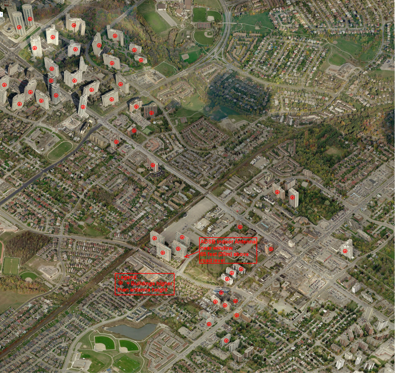
Question: Why my Receiver Range plot by VRS has large number of spikes (sudden drop in range) in various directions?
VRS-receiver range-18hr grab.png
Answer: Large number of buildings, much higher (100 feet to 300 feet) than height of my antenna (65 feet), all around my building.
My own building & 3 adjacent buildings (all 230 feet high), provide the worst obstruction, completely cutting-off 180 degrees of view
See bird's eye view of the area below.
.Last edited by abcd567; 2014-05-19, 01:20.Comment
-
SBSplotter - Another way of plotting receiver range
1. Using jetvision's "RTL-1090" & "SBS Plotter 1" softwares, collect receiver range data for the desired period.
(Click here to Download SBS Plotter 1 - http://jetvision.de/sbs/sbsplotter1.zip)
2. Massage the data using technique described in http://sonicgoose.com/superimpose-po...-google-earth/,
3. Skip the last step of sonicgoose page, and do not create a .kml file for Google Earth by GPS Visualizer site.
4. Instead, plot the range data in Google Map using GPS Visualizer's Map site http://www.gpsvisualizer.com/map_input?form=google. Set the option "Initial Map type" to "Google Street Map", and "Colorize by" to "Track". The map will be produced in a browser window instead of Google Earth.
A screenshot of map produced by me using above method is given below.
SBSplotter-receiver range-18hr grab.pngLast edited by abcd567; 2014-05-19, 02:54.Comment
-
don't forget about beaglebone black, if a pi runs out of steam.
Pretty sure what ever you will have to do to get a windows binary running on a Linux platform will have to be done for both a pi and beaglebone and probably not strait forward.
Another alternative that would be easiest as it would be running windows already is one of the NUC based mini PC's. Just google NUC. If you got an older one it wouldnt be that fast or powerful but would be more than enough.
or if your feeling sneaky set the laptops screen saver to a blank screen and colour the LED's in with a marker pen if its quiet enough she might never spot it T-EGLF8
Comment
-
We haven't heard much from the "Farnborough" guys recently with their RG402 experiment. Any news?T-EGUB1Comment
-
We haven't gone away, just quite busy at the moment, also the analyser is being used elsewhere, limiting our access to it.Originally posted by trigger View Post
however I did get to try out the prototype on it at the end of last week, it is looking good, but the dip is in the wrong place, I need to shorten all the sections to raise the resonant frequency,
I have masses of photos and when we have worked out the correct element lengths to allow for the effect of the housing I will try to knock up a PDF document with all the details.
Ben.
(Also I have to admit I have spent some time recently playing about with my home-brew 'Open Glider Network' station).FR24 F-EGLF1, Blitzortung station 878, OGN Aldersht2, PilotAware PWAldersht, PlanePlotter M7.Comment
-
Thank you SpaxmoidJAm for your valuable advise and contribution to the discussion.Originally posted by SpaxmoidJAm View PostComment
-
Hi Ben,Originally posted by F-EGLF1 View Post
Just checking Looking forward to your photos.
I had a quick look at Open Glider Network. As we have almost no gliders over here, that is not something I'll be pursuing. Interesting though.T-EGUB1Comment
-
Thanks. Waiting for your feedback/pdf document.Originally posted by F-EGLF1 View Post
It would be very interesting if another CoCo using commonly available RG6 cable is made & tested.
The comparison of results of tests of CoCos made of RG6 & RG402 will show how much is the advantage of using RG402 over using RG6.
I would love to do this comparison myself, but the only test instruments I have is a multimeter.
Comment
-
I think the main advantage would not be in performance, but more in ease of construction.Originally posted by abcd567 View Post
With 402 it can be cut to precise lengths with no wispy bits of screening, also because it is PTFE insulated it can be soldered without melting. (The shield is even pre-tinned!)
This should result in a design that is repeatable without needing any expensive test kit, just careful measuring and quite easy soldering.
Ben.FR24 F-EGLF1, Blitzortung station 878, OGN Aldersht2, PilotAware PWAldersht, PlanePlotter M7.Comment
-
Thanks Ben for your reply. I fully agree with you, as this exactly was my opinion. I just wanted to clear this point to many hobbyists who have pinned a high hope on RG402 for an excellent performance (Gain & SWR). The main advantage of RG402 is an easy to construct repeatable design, which can be fairly accurately copied by an amatuer/hobbyist. No VF guessing & no shorts caused by wispy bits of braid wiresOriginally posted by F-EGLF1 View PostComment
-
This "is this coax better than the other" discussion is confusing me...
Given that an antenna made from 1m of RG6 costs 7 pence (uk) and one made from RG402 would be 20 pounds... over 25 times the cost!!
my 7p job covers over 150 miles... So why try for more?
plus, we are in a network that has cells way smaller than this....
If its just for kicks, then why not use Andrews heliax? wider bandwidth and costs a load more ;-)
Sent using Tapatalk from my ZX81Last edited by Rooster; 2014-05-19, 23:02.Comment
-
@F-EGLF1
Ben, you were damn right when you said you want to make the coco measurements accurate to fraction of a millimeter level.
I have just run a simulation of an 8-element CoCo (air insulated), which had an element length of 137mm. I varied the length between 134mm and 140mm in steps of 1mm, and results are astonishing! The CoCo is highly intolerant to dimension inaccuracies. Even 1mm error in dimension can make it's performance miserable!
Please see below the screen shots of simulation with element length varying from 134mm to 139 mm.
Image 1 of 2
CoCo 8 elements - Dimension Tolerance 1.png
image 2 of 2
CoCo 8 elements - Dimension Tolerance 2.pngLast edited by abcd567; 2014-05-20, 05:00.Comment
-
Originally posted by Rooster View Post
The cable "Andrew Heliax" will make a very sturdy CoCo
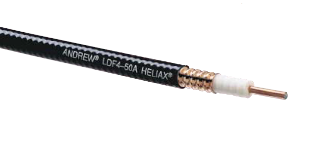
Outer Conductor: Copper
Inner Conductor: Copper-Clad Aluminum
Diameter over Jacket, 0.63 inch /16 mm
Diameter over Copper Outer Conductor: 0.55 inch / 14 mm
Diameter Inner Conductor: 0.189 inch / 4.6 mm
Impedance: 50 � 1 ohms
Maximum Frequency: 8.8 GHz
Foam Dielectric
Velocity Factor: 88%Last edited by abcd567; 2014-05-20, 04:53.Comment
-
This has nothing to do with one being better than the other, it is down to designing one that can be made by someone with basic tools to a pre-tested design, it is hard to get repeatable accuracy with RG6, especially if you are soldering the joints.Originally posted by Rooster View Post
Also the price is a LOT less than you quote, RG402 is only around �3 per meter including postage, a small sum to pay for easier construction.
Ben.FR24 F-EGLF1, Blitzortung station 878, OGN Aldersht2, PilotAware PWAldersht, PlanePlotter M7.Comment
Comment