 Tweet
Tweet
Hi ab cd, Good work! Glad you sorted the "bug".
-
T-EGUB1 -
Hi BenOriginally posted by F-EGLF1 View Post
The 65mm tap position shown on your drawing is OK. Simulation gives a figure of 66mm for lowest SWR.
Below are screenshots of the simulation.
Regards
abcd
Image 1 of 3 - Simulation output: Pattern, Gain, SWR
Ben's Franklin-pattern.png
Image 2 of 3 - Simulation output: Tap position sweep
Ben's Franklin-tap position.png
Image 3 of 3 - Simulation input: wire geometry, wire dia, frequency
Ben's Franklin-geometry input.jpg
Later addition:
Forgot to tell your wire lengths are ok
1/2 wavelength limbs = 1/2 x 299/868.3 = 0.172 m =172mm
Phasing stubs total length
required = 1/2 wavelength = 172mm
provided = 84mm+4mm+84mm = 172mm
Impedance matching stub:
required horizontal length = 1/4 wavelength = 172/2 = 86mm
provided = 86mm
required vertical gap between stub wires (center to center) = 3mm (practically difficult to construct and connect cable with such small gap between stub wires)
provided = 5mm is OK, still gives a decent SWR of less than 1.5Last edited by abcd567; 2014-05-21, 13:03.Comment
-
I did not try simulation of CoCos with Insulation as my software (4nec2) handles only air insulated wires.Originally posted by Ressy View Post
However couple of months ago I have made 4 CoCos (3.5-elements each) from same reel of coaxial cable, but each CoCo having a different element length. The reason was that I did not know the VF of cable. The element lengths were CoCo1: 11.0cm (VF=80%), CoCo2: 11.3cm (VF=82%), CoCo3: 11.6cm (VF=84%) and CoCo4: 11.9cm (VF=86%). I put them on trial run one by one, each for 48 hours. I found the best result was given by 11.6 cm, indicating that the cable I used has a VF of 84%, but this result is not universally applicable to all RG6 models & manufacturers. It only applies to the cable reel I used for this experiment.Last edited by abcd567; 2014-05-21, 13:44.Comment
-
adbc567, is 7element with 3/4 wave length element on the bottom odd num of elements of 1/2 wave and 1/4 wave length element on the top (shorted) is better or odd number of 1/2 elements with shorted 1/4 element on the top better? temp.jpgRTL SDR : T-VEVZ1Comment
-
The picture below shows the incident which triggered my entry into the world of DIY antennas.
Otherwise I might have continued using stock antenna for ever.
DSC02173R.jpgComment
-
Can not say anything about this issue as never tried or even thought of a bottom 3/4 wavelength piece. Other experienced forum members may shed some light on this.Originally posted by charan View Post
I feel all jugglery at the bottom of Radarcape antenna is for:
(1) Coin size disc+4 down legs, matching a Balanced antenna with unbalanced coaxial (Balun) .
(2) A metallic sleeve on pipe, electrically connected to braid, to prevent the feedline braid from re-radiating the received signal which results in a negative feedback to the system.
Well all this is only my guess. Unless I study the subject in more detail, I cannot say anything with surety.Comment
-
hmm, but i tested with 3/4th element yesterday, and today i removed it and now testing, can say i have better performance without it.. have to check again.Originally posted by abcd567 View PostRTL SDR : T-VEVZ1Comment
-
Did you test bottom 3/4 with or without sleeve & balun?Originally posted by charan View Post
If you don't provide sleeve or balun, then the bottom 3/4 element is just a length of coax feedline.
The 1/2 element (1/4 wavelength) at top has a different function. It is for impedance matching/improving SWR.Comment
-
Many many thanks for this, I will keep the stub gap as small as reasonably possible, I just estimated the tap position at 75% of the length, good to have a more accurate measurement.Originally posted by abcd567 View Post
Ben.FR24 F-EGLF1, Blitzortung station 878, OGN Aldersht2, PilotAware PWAldersht, PlanePlotter M7.Comment
-
@F-EGLF1
Hi Ben
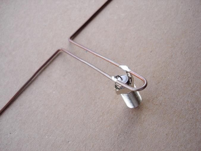
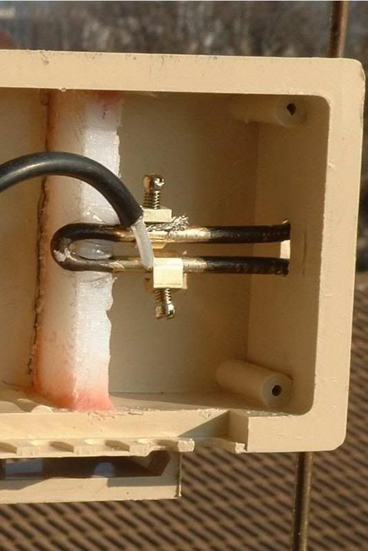
See pictures below showing various methods people have used to connect coax cable to Franklin.
What method you have used?
Comment
-
5mm is reasonable & practical. I am using 5mm with good results.Originally posted by F-EGLF1 View Post
If you try to reduce it, the stub wires may touch each other & the optimum tap position may shift few mm left or right.
Best keep it as in your diagram - 5mm.Comment
-
I have just spent my lunch hour getting my head around the sleeve baluns, now I know where I was going wrong! I did not fully realise the importance of the upper one and ended up going back to basics to model the impedance / reactance of the antennae, I simplified it down to an end-feed Franklin type with quarter wave ground plane stubs so I could visualise what was happening, (actually to tell the truth, I treated it as a TX antennae as it was easier to visualise voltage / current).Originally posted by abcd567 View Post
The lower balun provides a consistent low impedance feed point, without it then the feed cable could affect the antennae, the upper one does the same for the 3/4 wavelength section, without it you have a high impedance and it will not see the rest of the segments!!! So BOTH baluns are important.
I don't have any nice diagrams as this was done the old-fashioned way on the back of some scrap paper.
I also put my MK1 coco back on the analyser, and now realise why it did not perform as well as hoped, basically I made it too well and the bandwidth is too narrow, I will re-build it next week with the elements at 101%, 100% and 99% of the correct length, this should open out the dip to +-10 to 15MHz.
Picture attached showing MK1 with very sharp dip
Also I can confirm that the segments using RG402 need to be 95MM long with approx 1/2MM gap, I am away from work till next week, but I will post the results of the tweaked lengths as soon as I can.
Ben.image.jpgFR24 F-EGLF1, Blitzortung station 878, OGN Aldersht2, PilotAware PWAldersht, PlanePlotter M7.Comment
-
From the calculations I was doing today it is clear that the termination serves very different functions for odd or even numbers of elements, odd numbered segments end with high impedance and need a shorted stub, even numbered segments end with high reactance so need an open ended stub, (I think I have this the right way round).Originally posted by charan View Post
If you have 3/4 wavelength at the bottom then you MUST have both sleeve baluns for it to work (or at the very least the upper one), you only count the elements above it, otherwise you would probably get better results without it, but at the risk of greater mis-match between antennae and feeder.
Ben.Last edited by F-EGLF1; 2014-05-21, 17:32.FR24 F-EGLF1, Blitzortung station 878, OGN Aldersht2, PilotAware PWAldersht, PlanePlotter M7.Comment
-
i did not provided any sleeve or balun. can you give me the specs to make balun?Originally posted by abcd567 View PostRTL SDR : T-VEVZ1Comment
-
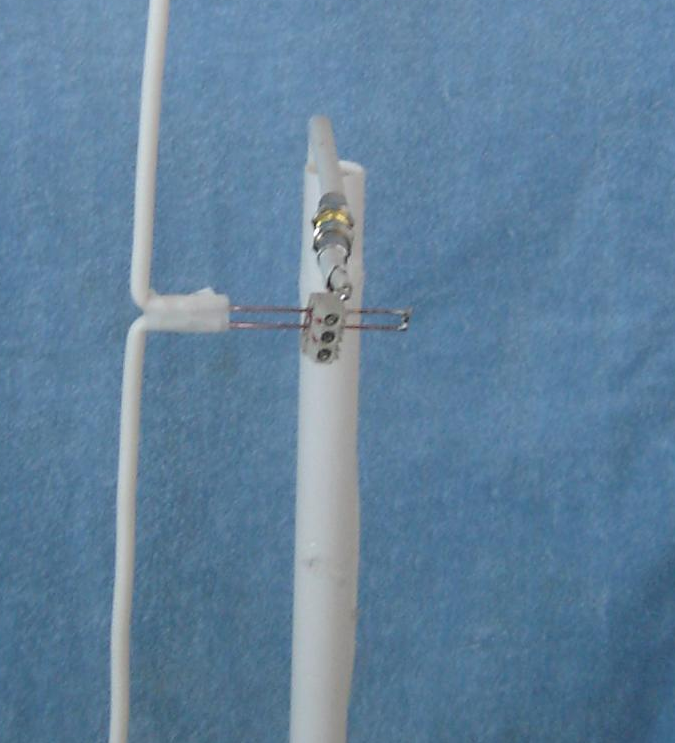
Now made it, but not got the R-Pi configured yet, it won't talk to my WiFi dongle, so I am going to have to use a network cable for now, pictures of setup and tap below, I will be ditching the cable between the antennae and the amp just as soon as I can get hold of an SMA M-M coupler.Originally posted by abcd567 View Post
image.jpgimage.jpg
Ben.FR24 F-EGLF1, Blitzortung station 878, OGN Aldersht2, PilotAware PWAldersht, PlanePlotter M7.Comment
Comment