-
Today I made a new 6-element CoCo. I put it to test WITHOUT amplifier and 12ft/ 4m piece of RG6 coax between CoCo and DVB-T USB Dongle + RPi combo. As usual results were poor (see Image 1 of 3).
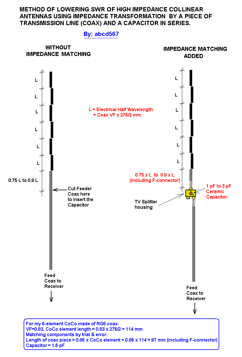
I then inserted a capacitor (1.5 pF ) and a piece of coax (length = 0.85 x 1/2 wavelength) between feed cable & CoCo, bringing it's Impedance down, and thereby improving its SWR. The performace increased considerably (see Image 2 of 3).
I found the length of coax piece & value of capacitor by trial & error, and a few trials only. If I would have tried more lengths & capacitors, I might have got even better results. The rule of thumb I use is that coax piece's optimum length is somewhere between 0.75 to 0.9 of 1/2 wavelength element of CoCo, & the capacitor 's optimum value lies somewhere between 1 pF and 3 pF.
Please see Image 3 of 3 showing the impedance matching arrangement.
The two screenshots of dump1090's gmap were taken with a difference of 2 minutes only, the time taken to insert/remove the capacitor.
IMAGE 1 of 3- dump1090 gmap, NO Impedance Matching, NO Amplifier
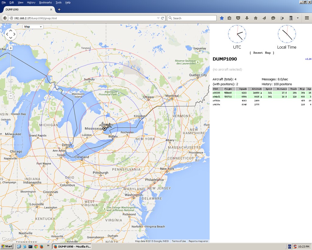
IMAGE 2 of 3 - dump1090 gmap, WITH Impedance Matching, NO Amplifier
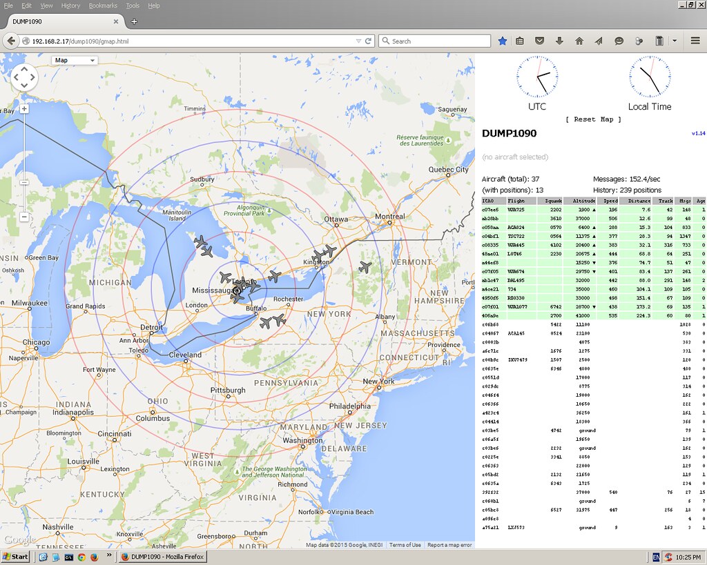
IMAGE 3 of 3 - Impedance Matching Arrangement
Leave a comment:
-
.
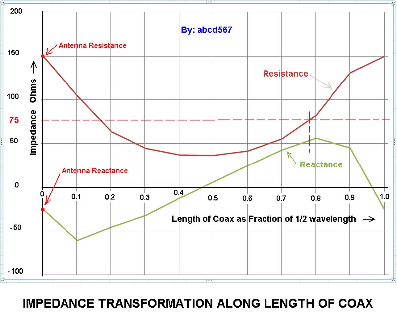
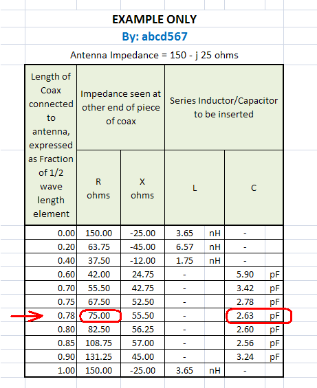
GRAPHICAL REPRESENTATION - IMPEDANCE TRANSFORMATION ALONG LENGTH OF COAX
Leave a comment:
-
IMPROVING PERFORMANCE OF A COCO BY LOWERING IT's SWR/IMPEDANCE
It is well known that a large number of DIY CoCo makers get frustrating results, and only a relatively small number get satisfactory or good results. Main reason is high impedance & resulting high SWR which causes the antenna to perform poorly even if it has a high Gain.
I have tried to find a method to ease out the SWR without using test instruments. I tested it and it gave me an improvement of about 25 to 35%., not optimal, but better than nothing.
Please see sketches below showing an example of impedance matching using this method. It results in using a piece of coax between 0.75 to 0.9 of the length of halfwave elements of CoCo, and a 2.5 pF Capacitor in series. It is applicable to most CoCos without using test equipments. It requires trying four pieces of coax of lengths (0.75 x VF x 138 mm), (0.8 x VF x 138 mm), (0.85 x VF x 138 mm) and (0.9 x VF x 138 mm), and keep the one which give better results than others. The length of coax piece includes length of F-connector also.
SKETCH 1 of 2 : IMPEDANCE TRANSFORMATION BY A PIECE OF COAX 0 to 1/2 WAVELENGTH LENGTH
SHETCH 2 of 2: IMPEDANCE MATCHING / SWR IMPROVEMENT METHOD
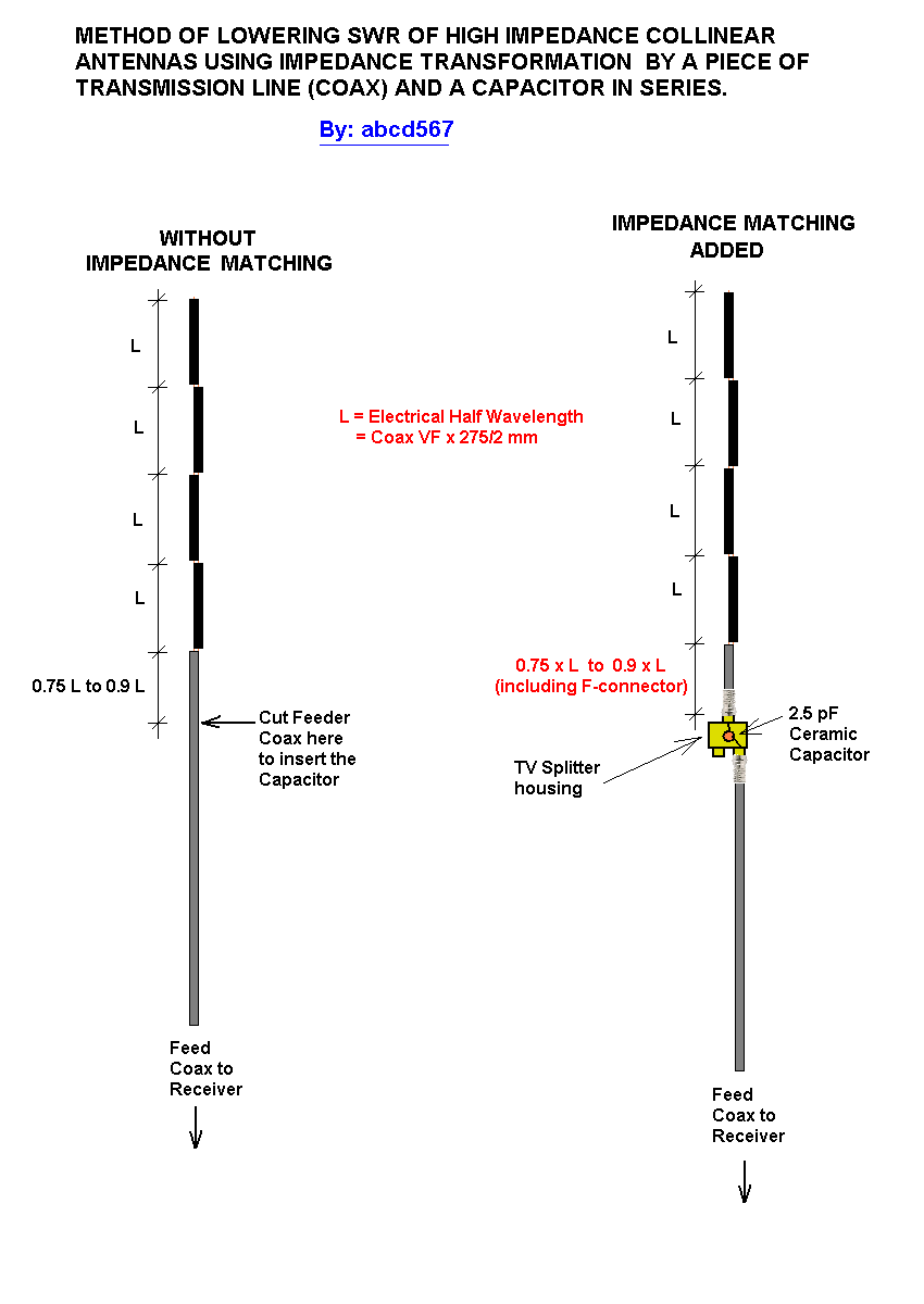
This method uses the fact that a piece of transmission line (Coax) transforms the impedance of antenna connected to it. The value of impedance seen at other end of coax depends on length of piece of coax. The impedance transforms in a cyclic manner, returnig back equal to antenna impedance every 1/2 wavelength. At a particular length in between 0 and 1/2 wavelength, the Resistance transforms to exactly the impedance of coax/receiver, and reactive component transforms from capacitive to inductive. At this point if a capacitor of appropriate value is inserted to cancel the inductive component to zero, only resistive component remains which is equal to system impedance, and stays same along remaining entire length of feed coax.
.Last edited by abcd567; 2015-08-10, 09:33.Leave a comment:
-
Whip2.JPG
I have been using this whip antenna for a while, it is a 3 element wire collinier, when covered with heatshrink it was detuned and needed 60mm trimmed from the top. Now it works perfectly. I also made a 9 element in the same way but the detuning from heatshrink was more severe, and there is not enough top element to trim down. I have been using this whip without any insulation material so it is affected by rain which detunes it .
Whip.jpg
I have been working on the de-tuning effect and the velocity factor of heatshrink , and have made another antenna, this time I have used a velocity factor of .94
I re-calculated all the formulas for the elements and the coils at .94 percent and covered it with heatshrink. Testing today and its working good, but I will need to do some trimming to get it A1 . Will report findings
Mike
Burnie, TasmaniaLeave a comment:
-
Over a period of last one and half years, I have modeled, simulated and optimized many different types of collinears using 4NEC2 & MMANA-GAL softwares. The simulations showed excellent Gain, SWR & Radiation Pattern for all these.Originally posted by SpaxmoidJAm View Post
As and when I modeled any antenna, I also built it and put to trial run. All failed miserably


Unfortunately I dont have fancy test equipment to test & tweak my antennas. The only test equipment I have is a multimeter which I purchased for $10.
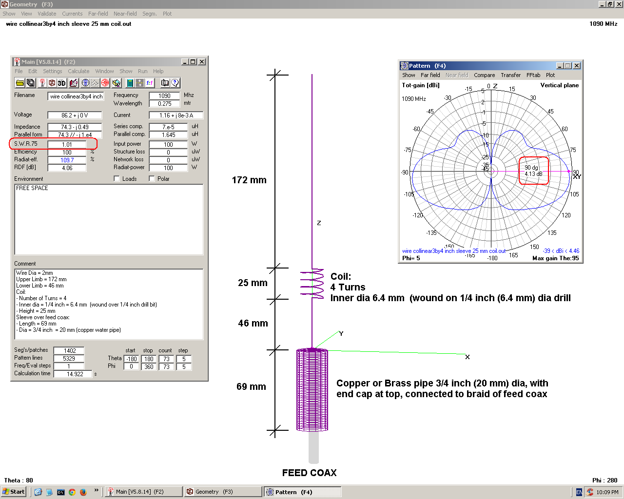
The latest example of "Excellent Simulation, Hopeless Prototype" is the wire collinear below, which I simulated & built this weekend, and this also failed miserably as usual
 Last edited by abcd567; 2015-08-09, 03:16.
Leave a comment:
-
well i fainally got around to testing the one i built of this (short story i forgot to order connectors also forgetting i built it)Originally posted by JLD View Post
the location i tested isnt the best suited nor was the coax i was using quite long enough but these things only make a minor difference to the antenna.
4.jpg
by moving me and the aerial i was only able to move things around by best a db and a few MHz.Leave a comment:
-
With recent improvement in my antenna gain, I have started picking up planes on ground at Toronto CYYZ airport. The strange thing is that the Toronto airport is TOTALLY behind a large high rise building when viewed from my antenna location, my antenna is lower than the surrounding buildings, inside my apartment, and I dont see any way the microwaves can penetrate and cross the large high rise building with left-over signal strength above the threshold of the receiver. I think the only possibility is multiple reflections from glazed glasses of buildings nearby, as shown in attache sketch.

Leave a comment:
-
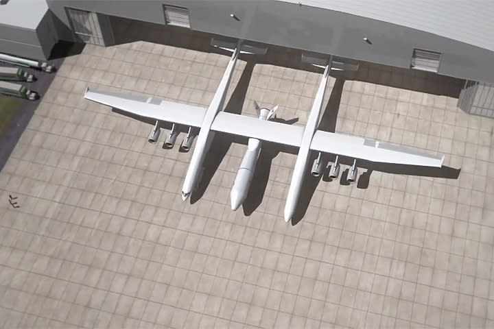
The largest plane Stratolaunch, nicknamed “Roc” features two fuselages, six Pratt & Whitney jet engines, 28 landing gear wheels, and a whopping 385 foot wingspan.
If you were to put the center of this airplane on a football field, its wingtips would extend beyond the goalposts by about 15 feet on each side.
Those dimensions make it 65 feet wider than the legendary “Spruce Goose” H-4 Hercules, 95 feet wider than the spaceship-carrying Soviet Antonov An-225, and 123 feet wider than the modern Airbus A380. In fact, it is being constructed using pieces of two already quite large planes–a pair of disused Boeing 747s.Leave a comment:
-
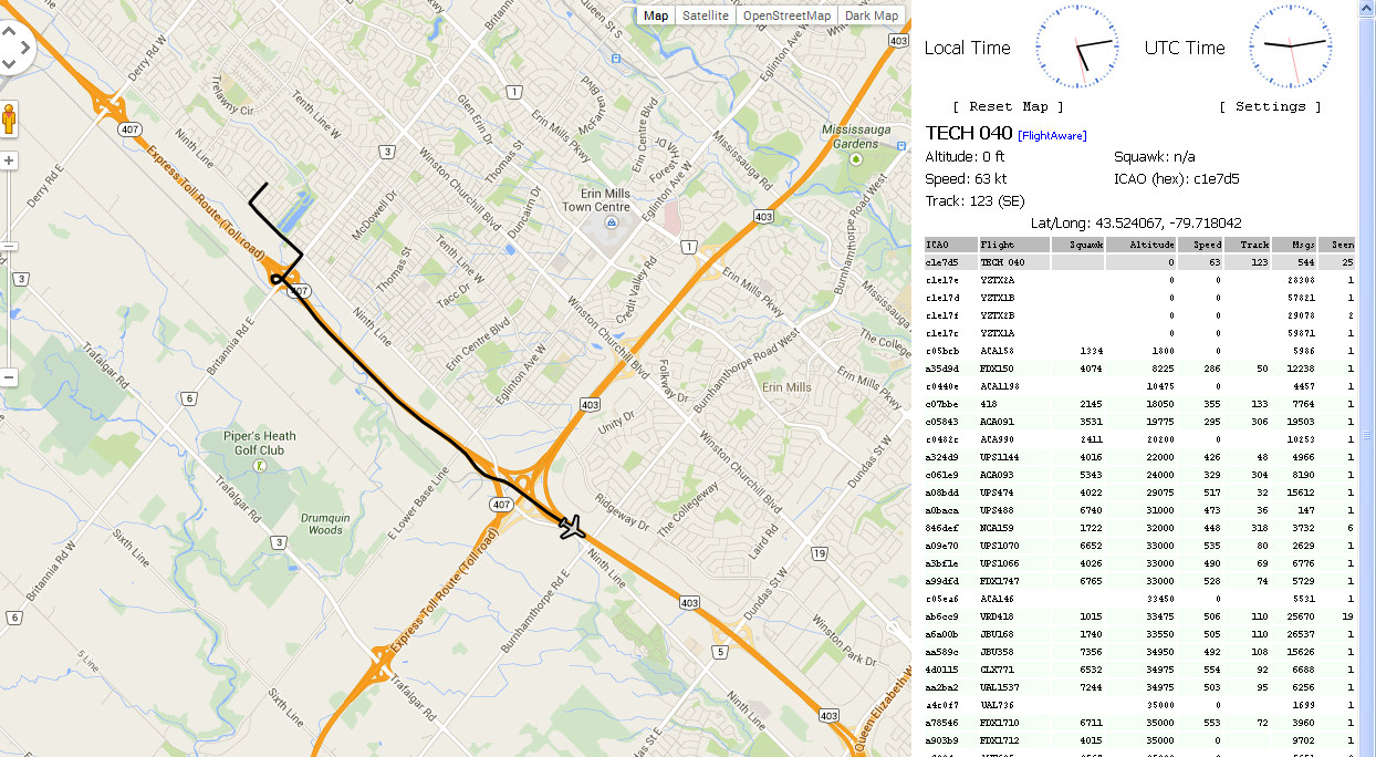
Here is the actual VeeLo test we did... max range was 5 Km and GPS data was highly accurate and could even tell me the lane the vehicle was driving (flying) in on the 407.
It's kind of funny to see a jet driving down the 407 !
Leave a comment:
-
Yes this is ground traffic and it is a transponder, but with a limited amount of power compared to an aircraft. This is what they are using to track ground vehicles, it's called a VeeLo made by Saab. The VeeLo's transmit only 20 watts so you have to be close to the airport to pick one up. I had a chance to test the range of a VeeLo with a representative from Nav Canada and it had a 5 Km range from my tower.

Originally posted by abcd567 View PostLeave a comment:
-
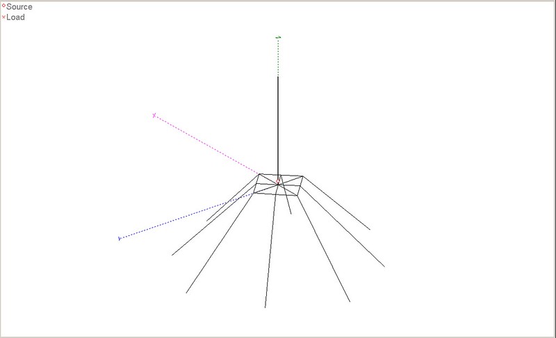
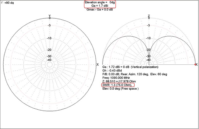
SIMULATION OF 2 DIY ANTENNAS
Simulation 1 of 2: SPIDER (8 Legged )
Gain = 1.7 dBi
SWR (75 ohms) = 1.3
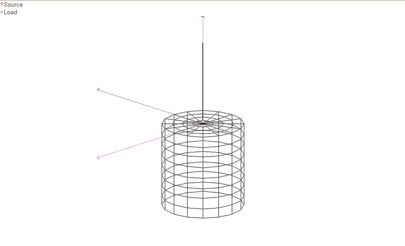
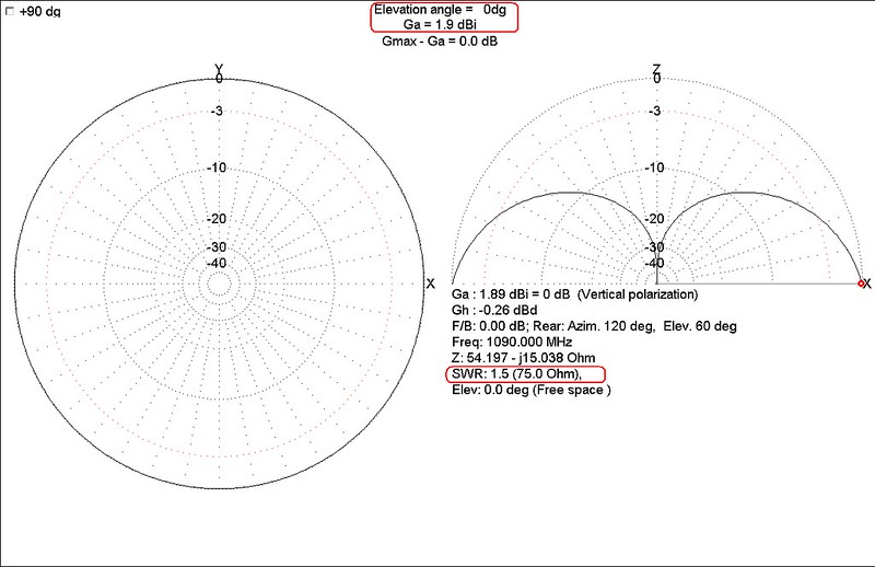
Simulation 2 of 2: CANTENNA
Gain = 1.9 dBi
SWR (75 ohms) = 1.5
Leave a comment:
- IMPORTANT NOTICE! Before you post on Flightradar24 forum you must read this important information about Flightradar24


Copyright (c) 2009-2019 by Flightradar24
Powered by vBulletin®
All times are GMT. This page was generated at 18:40.
Working...
X
We process personal data about users of our site, through the use of cookies and other technologies, to deliver our services, personalize advertising, and to analyze site activity. We may share certain information about our users with our advertising and analytics partners. For additional details, refer to our Privacy Policy.
By clicking "I AGREE" below, you agree to our Privacy Policy and our personal data processing and cookie practices as described therein. You also acknowledge that this forum may be hosted outside your country and you consent to the collection, storage, and processing of your data in the country where this forum is hosted.
Leave a comment: