Announcement

Collapse
No announcement yet.

best antenna

Collapse
X
 
  • Filter
  • Time
  • Show
Clear All
new posts

  • my circumstances quite different, outside mounting is a must (heavy attentuation through walls and double glazing treated glass) hence the quest for good performance but with ability to
    place antenna in radome of some type that failitates solid mounting - and i live quite close to sea (even my high quality stainless discone suffers!) .. so leaving any part of antenna exposed is not really an option.
    after tuning antenna in open air, im planning to see what effect placing it inside PVC pipe has.
    Comment


    • Originally posted by Birdie View Post
      Can you install your antenna on the roof top of the apartment ?

      I also live in an apartment - but I am lucky because I installed it on a 2.5 m stainless steel pole outside my window on the air con compressor's mounting bracket.
      Originally posted by gregy View Post
      my circumstances quite different, outside mounting is a must (heavy attentuation through walls and double glazing treated glass) hence the quest for good performance but with ability to
      place antenna in radome of some type that failitates solid mounting - and i live quite close to sea (even my high quality stainless discone suffers!) .. so leaving any part of antenna exposed is not really an option.
      after tuning antenna in open air, im planning to see what effect placing it inside PVC pipe has.
      Our Building Management do not allow any resident to install antenna on building's roof. If they would have allowed me, my antenna would have been 200+ feet above ground and above most of surrounding tall buildings.

      My windows are like aircraft windows: double glass, non-openable, but much bigger, almost like a wall.

      Comment


      • ...and from my experience ... most of the modern window heat/solar treatments .. also do a great job of attenuating RF (particularly in the higher freq bands ... where we are interested )
        .. but we deal with what we have to in the best way possible ! thats the creative engineering challenge.

        Comment


        • Originally posted by gregy View Post
          my circumstances quite different, outside mounting is a must (heavy attentuation through walls and double glazing treated glass) hence the quest for good performance but with ability to
          place antenna in radome of some type that failitates solid mounting - and i live quite close to sea (even my high quality stainless discone suffers!) .. so leaving any part of antenna exposed is not really an option.
          after tuning antenna in open air, im planning to see what effect placing it inside PVC pipe has.
          People have said

          put a short section of your PVC pipe alongside a cup of water and zap it for a couple of minutes, if the pipe gets noticeably warm it's absorbing signal.

          Fibreglass tube - uncoloured - may be better (probably depends on the resin materiel or the pigments used)

          Comment


          • Originally posted by gregy View Post
            ...and from my experience ... most of the modern window heat/solar treatments .. also do a great job of attenuating RF (particularly in the higher freq bands ... where we are interested )
            .. but we deal with what we have to in the best way possible ! thats the creative engineering challenge.
            You are right. We have to find a way to manage with whatever resources available, and use our ingenuity & skills to navigate through the odds & obstacles.

            When I got my first DVB-T USB Receiver, the very first thing I did was to replace my stock monopole antenna (which came with the USB Dongle), by a half wavelength DIY dipole, the tiniest & easiest antenna to make, and which has an impedance of 75 ohm without any tuning/maching elements. This antenna perfectly matched with my system & gave me SWR=1.

            However the gain of halfwavelength dipole was low i.e 2.2 dBi. My window glass & walls attenuated the signal. My RG6 Coax from window to my room was 50 feet, and of commercial grade, and has considerable attenuation. Both put together ate up all the tiny 2.2 dBi gain of my dipole.

            I did not run after a good antenna. Instead, my next step was to add an in-Line amplifier which I purchased from a Satellite Antenna shop for $4 & a DC adapter for $5. I could not find DC inserter in my neighborhood stores, so I made it myself using cheap parts (tv splitter+inductor+capacitor) for a total of about $3.

            The amplifier had a gain of 13-18 dB, which was sufficient to cover (1) the attenuated indoor signal, (2) the coax losses, and (3) the weak pre-amp of the USB DVB-T Receiver. As a result I started getting planes as far as 400 kms.

            Later I started to experiment with higher gain antennas like Franklin Collinear, Coaxial Collinear, Cantenna (sleeved dipole), Coil Loaded Dipoles etc.

            Comment


            • Originally posted by abcd567 View Post
              You are right. We have to find a way to manage with whatever resources available, and use our ingenuity & skills to navigate through the odds & obstacles.

              When I got my first DVB-T USB Receiver, the very first thing I did was to replace my stock monopole antenna (which came with the USB Dongle), by a half wavelength DIY dipole, the tiniest & easiest antenna to make, and which has an impedance of 75 ohm without any tuning/maching elements. This antenna perfectly matched with my system & gave me SWR=1.

              However the gain of halfwavelength dipole was low i.e 2.2 dBi. My window glass & walls attenuated the signal. My RG6 Coax from window to my room was 50 feet, and of commercial grade, and has considerable attenuation. Both put together ate up all the tiny 2.2 dBi gain of my dipole.

              I did not run after a good antenna. Instead, my next step was to add an in-Line amplifier which I purchased from a Satellite Antenna shop for $4 & a DC adapter for $5. I could not find DC inserter in my neighborhood stores, so I made it myself using cheap parts (tv splitter+inductor+capacitor) for a total of about $3.

              The amplifier had a gain of 13-18 dB, which was sufficient to cover (1) the attenuated indoor signal, (2) the coax losses, and (3) the weak pre-amp of the USB DVB-T Receiver. As a result I started getting planes as far as 400 kms.


              Later I started to experiment with higher gain antennas like Franklin Collinear, Coaxial Collinear, Cantenna (sleeved dipole), Coil Loaded Dipoles etc.
              This is an excellent antenna to start with, linked to a dongle & raspberry pi - once people have this they have an excellent working platform to upgrade from.

              Comment


              • Originally posted by tucco View Post
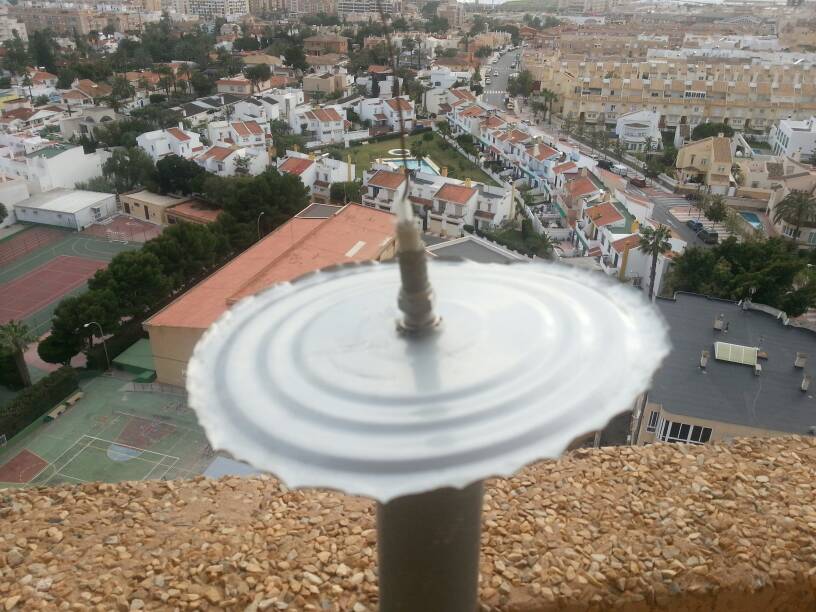
                Mine is made with 33cm unshielded TV coax and as a ground plane the bottom of a thunafish tin.


                More than 200nm.
                Enviado desde mi GT-N7100 usando Tapatalk 2
                I found this simple and easy to make antenna from another thread in FR24 Forum.
                The Range mentioned in this post (200nm) is remarkable for such a simple antenna.
                Last edited by abcd567; 2014-09-30, 08:10.

                Comment


                • [QUOTE=abcd567;56757](1) Solder wipe is actually small scale tinning, an alternative to factory tinned copper wire. It is a very practical solution if wire length is not large, which is your case.

                  (2) Waiting to see results of your CoCo project.

                  (3) A close look of your spider antenna photo showed that the ground plane wires are much longer than the quarter-wave vertical whip. Most of designs of spider antenna I have seen recommend ground plane wires to be quarter-wave length.

                  I have taken measurement of your spider antenna photograph, reference being the vertical whip which I took 69mm long, and used to scale other dimensions. I found your ground plane wires are 90mm long, the metallic Flange to which the ground plane wires are soldered is 36mm dia, and the ground plane wires are bent down 45 degrees.

                  I then modeled and ran computer simulation with 90mm long ground plane wires.
                  The results were Gain = 6.45 dBi, SWR = 8.

                  Since the SWR was very high, I ran the simulation again, this time using ground plane wire length of 69mm (quarter-wave length).
                  The results were Gain = 5.7 dBi, SWR = 1.94.

                  Hi all not sure if i got the reply with quote right but just an update. My spidertenna does have 69mm ground plane wires not 90mm as scaled, and plate they are soldered to is 30mm in diameter, just for clarification. I have pulled antenna down and replaced with 8 element coco just today. Will keep you posted regarding range. As for old spidertenna, well lets say you woudn't notice it in a patch of grass its that green. Ill give her a clean up and "Tin" it as decided/suggested. Will take a pic to show its sad state. I would love to get back to the range she gave when i first installed
                  Thanks
                  Steve P

                  Comment


                  • Oh and one other thing in pics on page 163 i see loops in cable. What sort of affect would this have and would the amount of loops make a difference??
                    Cheers

                    Comment


                    • Originally posted by Stephen P View Post

                      Hi all not sure if i got the reply with quote right ............
                      Steve P
                      While typing your message, you somehow deleted [ /QUOTE ] at the end of quoted message. This resulted in quoted message not appearing as normally it does (i.e. in a light-blue box). All quoted messages start with [ QUOTE ] tag and close with [ /QUOTE ] tag.

                      Comment


                      • Originally posted by Stephen P View Post
                        Oh and one other thing in pics on page 163 i see loops in cable. What sort of affect would this have and would the amount of loops make a difference??
                        Cheers
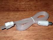
                        It is a 1:1 choke "balun".
                        It's function is to help eliminate RF currents (also called common mode currents) from flowing on the outside of coaxial cable braid.
                        It uses the principle of choke action.

                        It is mainly used with Transmitting antennas. The balun (choke), assures that the antenna, and not the feed line, is doing the radiation!

                        Increasing the number of turns (loops) or increasing the dia of loops increases the choking effect.
                        There are 1001 ways people make it.
                        Please see photos below:

                        . . . . . .
                        Last edited by abcd567; 2014-09-30, 09:12.

                        Comment


                        • Thanks for clarification, Pic 3 in above post is what i first looked at for antenna setup before researching and deciding on spidertenna. Personally i like setup of pic 5, Nice work, I wish. But pic 6 is the type of loops I'm talking about(possibly excess cable) as there seems to be no specifics applied to loops and taping compared to others depicted. Also commented that its usually used in transmitting, but as an average joe blow user RECEIVING not transmitting am still curios as to what excess loops could do to signal. After taking spidertenna down for service and temporarily installing new coco i have a loop of excess cable atop the mast and am figuring it would make a difference. Trying to find a solution to mast and cable connection so as to apply new antennas without changing cabling positions (excess cable in varying degrees of loops) . I'm using a variety of Aussie TV and Cable(F) connectors plus gender benders to add or subtract new antenna styles to the existing system. Any Thoughts welcome as always.

                          Comment


                          • [QUOTE=abcd567;57155]
                            The amplifier had a gain of 13-18 dB, which was sufficient to cover (1) the attenuated indoor signal, (2) the coax losses, and (3) the weak pre-amp of the USB DVB-T Receiver. As a result I started getting planes as far as 400 kms.

                            ... Yes and No...

                            some info relevant to an amplifier placed at antenna - often reffered to as "LNA" low noise amp or "TTA" tower top amp.
                            The purpose of a tower top amplifier (TTA) is to improve receiver sensitivity at a site by compensating for the loss of the coaxial cable that connects the receive antenna to the system.
                            One misconception of using a TTA is thinking that it will improve an already noisy site. Using a TTA, at a noisy site, will only amplify the noise and will result in more interference in the receiver
                            The main purpose of the TTA is to compensate for the loss of the feedline that runs to receiver. The amplifier in the TTA, amplifies the weak signal that is received before it enters the lossy feedline. A TTA is more prevalent in UHF and above, since the transmission line losses are higher. A TTA will not usually improve sensitivity, other than reducing the effects of the line loss.
                            The TTA will set the overall noise figure and system sensitivity of the site. The overall noise figure represents the bottom line on how well the system will perform. Lower noise figure yields better system receiver sensitivity.


                            The SDR dongle has a quite high preamp gain (as evidenced by it usually operating below the max gain to give optimum results), but at the higher settings the S/N ratio can be observed to reduce (noise from SDR and its power supply et al contributes and .... gets amplified as well as avail signal)

                            The loss that you suffer in the wanted signal by wall/window attenuation cannot be compensated by the amplifier, as it can only amplify the available signal
                            (& local noise) ... hence it has to work with available S/N ratio...
                            whatever can be done with antenna performance (useful gain) and height etc ... yields
                            a higher signal .. vs noiise
                            However what it does (usually) present, is a better Noise figure than the receiver (in this case the SDR dongle)
                            AND amplifies signal prior to the cable loss - hence its apparent benefit is much higher when using lossy cable - as compared to more $ and lower loss cable.
                            Hence the significant improvement you experience, is most likely from the NF and amp gain - ahead of the cable loss.
                            There is no substitute for getting a better performing antenna as high and clear as possible , once the signal is attenuated by walls etc ... it cant be recovered without also amplifying noise..
                            Last edited by gregy; 2014-09-30, 14:56.

                            Comment


                            • @Stephen P:

                              TWIN-LEAD / LADDER-LINE
                              Two wire circuits carry two currents, one on each wire. Example is twin wire transmission line. If the load (e.g. antenna) is balanced, the current is balanced i.e the currents in two conductors are equal and opposite.

                              .


                              COAXIAL CABLE
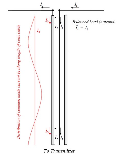
                              Although the coaxial cable also has two conductors, but it carries 3 currents:
                              (1) current in central core.
                              (2) current on the INNER SURFACE of the shield/braid.
                              (3) current on the OUTER SURFACE of shield/braid.


                              Currents (1) & (2) are balanced i.e. equal and opposite, just like twin wire. The current (3) is independent of currents (1) & (2) and is called common mode current.

                              If coax is connected between a balanced antenna and a transmitter, the transmitter pumps in a balanced set of current (1 & 2) whose electromagnetic field is confined totally inside the coax. This set of current does not radiate any RF energy in air, and delivers it all to the antenna. It is the antenna which radiates all this delivered RF energy in the air.

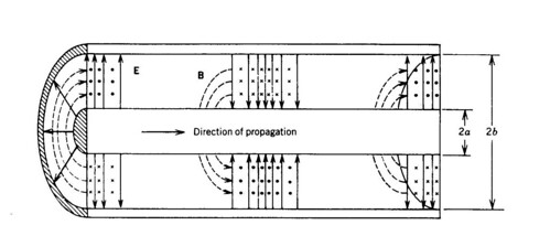
                              The sketch below shows the electromagnetic field produced by inner currents (1) & (2). This field is totally confined to the space between core and shield, and is blocked by the shield to go out.


                              The transmitter also pumps in the third current (current 3) on the outer surface of coax, and the outer surface of coax radiates all the RF energy contained in current (3) into air, effectively acting as another antenna. This affects the radiation pattern, gain & swr of the antenna. Choke balun blocks the current (3) without affecting currents (1) & (2), and enable maintening the designed radistion pattern, gain & swr of the antenna.

                              For receiving antenna the situation is simmilar except that here the antenna as well as the outer surface of braid intercept incoming RF energy. The incident RF wave on antenna genrates and pumps currents (1) & (2) into receiver. The incident RF wave on braid generates and pumps current (3) into receiver. The braid, acting as second receiving antenna, greatly modifies the designed radiation pattern, gain & swr of the antenna. Choke balun blocks current (3) generated by outer surface of braid, without affecting currents (1) & (2) generated by antenna.

                              The cox has 3 currents because of its special physical constrution. The electromagnetic field created by inner currents are totally confined inside of shield, while the RF waves outside are blocked from entering the inner space of coax and only interact with outer surface of the shield.
                              Last edited by abcd567; 2014-10-01, 14:32.

                              Comment


                              • Originally posted by gregy View Post
                                ... Yes and No...
                                What I described was best under my conditions. I never mentioned or meant that this is the best solution, universally applicable under all conditions.

                                My conditions are:
                                (1) Strictly indoor.
                                (2) Large glass windows around antenna location. Therefore there is no attenuation of walls or roof. The RF signal has to cross only un-glazed, slightly tinted window glass to reach the antenna.
                                (3) Very low noise area, as no noise genrating or interfering installations nearby (such as cell phone tower or any other emi generating equipment).
                                (4) Long run (50ft/15m) of cheap quality coax between antenna & receiver (DVB-T USB dongle).

                                I consider that under these conditions, what I did was most suitable and cost effective.

                                Originally posted by gregy View Post
                                .....The SDR dongle has a quite high preamp gain........
                                I dont agree. Costlier professional receivers like Beast or FR24 supplied receiver have far better gain, sensetivity & selectivity than DVB-T USB Dongle.
                                Last edited by abcd567; 2014-10-01, 01:20.

                                Comment

                                Working...
                                X