 Tweet
Tweet
I have received an email on my email address "abcd567@hotmail.com", which has valuable information about CoCos. I am copying it below:
.
EDIT: Email sender's name removed as per sender's request
Captain ABCD567,
I tried adding a comment to the fr24 forum "best antenna" thread, but it seems my message was lost in moderation. I thought you might find some of this interesting:
The above from:

More on element spacing at:
It seems most people agree that a "free-space" tuned CoCo will be detuned by placing it inside a plastic tube. However, if this detuning makes the antenna "appear" too long, the detuning might not be disastrous, because longer-than-λ/2 elements are not necessarily that bad? And with a "too long" antenna, the apparent element spacing would also be longer, which might actually be beneficial. All in all, to PVC or not to PVC might be a moot point?
Also, simulating insulated wires is supposed to be possible in 4NEC2, see this post:

It's a bit disheartening to see how much trouble people have getting these coco designs to work, but I'm going to give it a shot anyway. Or actually three shots; I would like to try 1) classic cable coco, 2) rod/pipe air dielectric vf 1.0 coco, 3) 0.75λ; element spacing coco. It might be a month until I have time to actually do this.
Cheers from Norway,
XXXXX
I tried adding a comment to the fr24 forum "best antenna" thread, but it seems my message was lost in moderation. I thought you might find some of this interesting:
LENGTH AND PHASING.—Although the 1/2 wavelength is the basis for the collinear element, you will find that greater lengths are often used. Effective arrays of this type have been constructed in which the elements are 0.7 and even 0.8 wavelength long. This type of array provides efficient operation at more than one frequency or over a wider frequency range. Whatever length is decided upon, all of the elements in a particular array should closely adhere to that length. If elements of different lengths are combined, current phasing and distribution are changed, throwing the system out of balance and seriously affecting the radiation pattern.
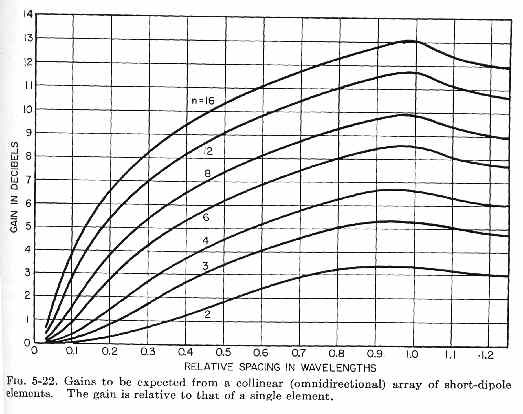
SPACING.—The lower relative efficiency of collinear arrays of many elements, compared with other multi-element arrays, relates directly to spacing and mutual impedance effects. Mutual impedance is an important factor to be considered when any two elements are parallel and are spaced so that considerable coupling is between them. There is very little mutual impedance between collinear sections.
Where impedance does exist, it is caused by the coupling between the ends of adjacent elements. Placing the ends of elements close together is frequently necessary because of construction problems, especially where long lengths of wire are involved.
The effects of spacing and the advantages of proper spacing can be demonstrated by some practical examples. A collinear array consisting of two half-wave elements with 1/4-wavelength spacing between centers has a gain of 1.8 dB. If the ends of these same dipoles are separated so that the distance from center to center is 3/4 wavelengths and they are driven from the same source, the gain increases to approximately 2.9 dB.
A three-dipole array with negligible spacing between elements gives a gain of 3.3 dB. In other words, when two elements are used with wider spacing, the gain obtained is approximately equal to the gain obtainable from three elements with close spacing. The spacing of this array permits simpler construction, since only two dipoles are used. It also allows the antenna to occupy less space. Construction problems usually dictate small-array spacing.
More on element spacing at:
It seems most people agree that a "free-space" tuned CoCo will be detuned by placing it inside a plastic tube. However, if this detuning makes the antenna "appear" too long, the detuning might not be disastrous, because longer-than-λ/2 elements are not necessarily that bad? And with a "too long" antenna, the apparent element spacing would also be longer, which might actually be beneficial. All in all, to PVC or not to PVC might be a moot point?
Also, simulating insulated wires is supposed to be possible in 4NEC2, see this post:
It's a bit disheartening to see how much trouble people have getting these coco designs to work, but I'm going to give it a shot anyway. Or actually three shots; I would like to try 1) classic cable coco, 2) rod/pipe air dielectric vf 1.0 coco, 3) 0.75λ; element spacing coco. It might be a month until I have time to actually do this.
Cheers from Norway,
XXXXX
EDIT: Email sender's name removed as per sender's request


Comment